2 Global Alignment
2.2 Iterative Application of Global Alignments
2.3 Procedures to Determine Global Alignment Parameters
2.4 Simulation of Non-Ideal Detector Geometries
2.5 The Global Alignment Interface
2.1 Global Alignment of Detector Components
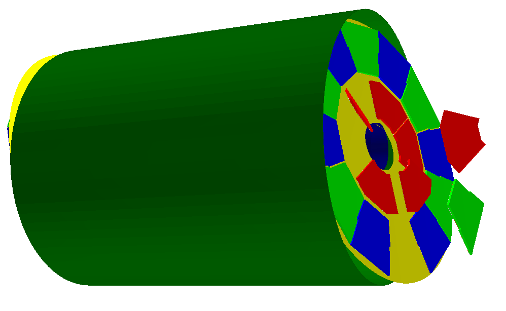
In this section the backgrounds of the Global Alignment is described. Alignment parameters never apply in the same way to all placements of the same volume in this hierarchy. Hence, to (re-)align a volume in the hierarchy means to logically lift a full branch of placements from the top volume down to the element to be (re-)aligned out of this shared hierarchy and apply a correction matrix to the last node. This procedure is illustrated in Figure 5. Re-alignment of volumes may occur at any level. In the above example of a TPC this results in the following effects:
-
A realignment of the entire subdetector, i.e. the TPC as a whole, would affect consequently move all contained children with respect to the top level coordinate system. An example is shown in Figure 5 (a). A movement of the subdetector would affect all transformation between local coordinates of any part of the subdetector to the top level coordinate system. Such effects would be visible at all stages of the data processing e.g. when translating signals from particles into global coordinates.
-
A realignment of parts of a subdetector affects only the partial subdetector itself and child volumes at lower levels. As in the example, where the entire subdetector is moved, here only the sectors on one side of the TPC would be affected as shown in Figure 5 (b).
-
In Figure 5 (c) within one end-cap of the TPC individual sectors may not be positioned at the ideal location (Figure 5 (c) exaggerates: ”flying sectors” are a rather rare case in reality). Finally also the sectors itself could be fragmented and be assemblies of other shapes, which are not ideally placed and may need correction.
The origin of the volume misplacements may be many-fold:
-
Elements may be weak and assembled parts move due to weak support structures. This is a common problem e.g. for tracking detectors, where heavy and solid structures dramatically influence the measurement result. Misplaced sectors could e.g. be the consequence of a deforming end-cap frame due to the weight of the sectors.
-
Environmental conditions such as the temperature may influence the position or the shape of a volume.
-
Some of the measurement equipment may be moved from a parking position into a data taking position such as the two halves of the LHCb vertex detector. Whereas the position of the sensors on each half are known to a very high precision, the position of the absolute position of the two halves with respect to the full experiment may change after each movement.
Changes to the volume placement do not only affect sensitive material i.e. detector components with an active readout, but also passive material. The placement of any volume, passive or active, may be corrected using DDAlign . The determination of the alignment parameters of passive components however may be more difficult in the absence of located signals resulting e.g. from the traversal of a track.
All effects resulting from such causes obviously need to be corrected in order to fully explore the capabilities of the detection devices and to minimize measurement errors. In general any deviation from the ideal position of a volume can be described by two elementary transformations:
-
a translation
-
a rotation around a pivot point.
giving a full transformation matrix of the form:
|
| (1) |
where
-
is the full transformation in 3D space containing the change to the exiting placement transformation. The existing placement is the placement transformation of the volume with respect to the mother volume.
-
is a translation specifying the position change with respect to the mother volume.
-
describes a rotation around a pivot point specified int he mother volume’s coordinate system.
-
is the translation vector from the mother volumes origin to the pivot point. The concept of a pivot point does not introduce a new set of parameters. Pivot points only help to increase the numerical precision.
Most of the changes do not require the full set of parameters. Very often the changes only require the application of only a translation, only a rotation or both with a pivot point in the origin. These simplifications are supported in the user interface described in Section 5.
2.2 Iterative Application of Global Alignments
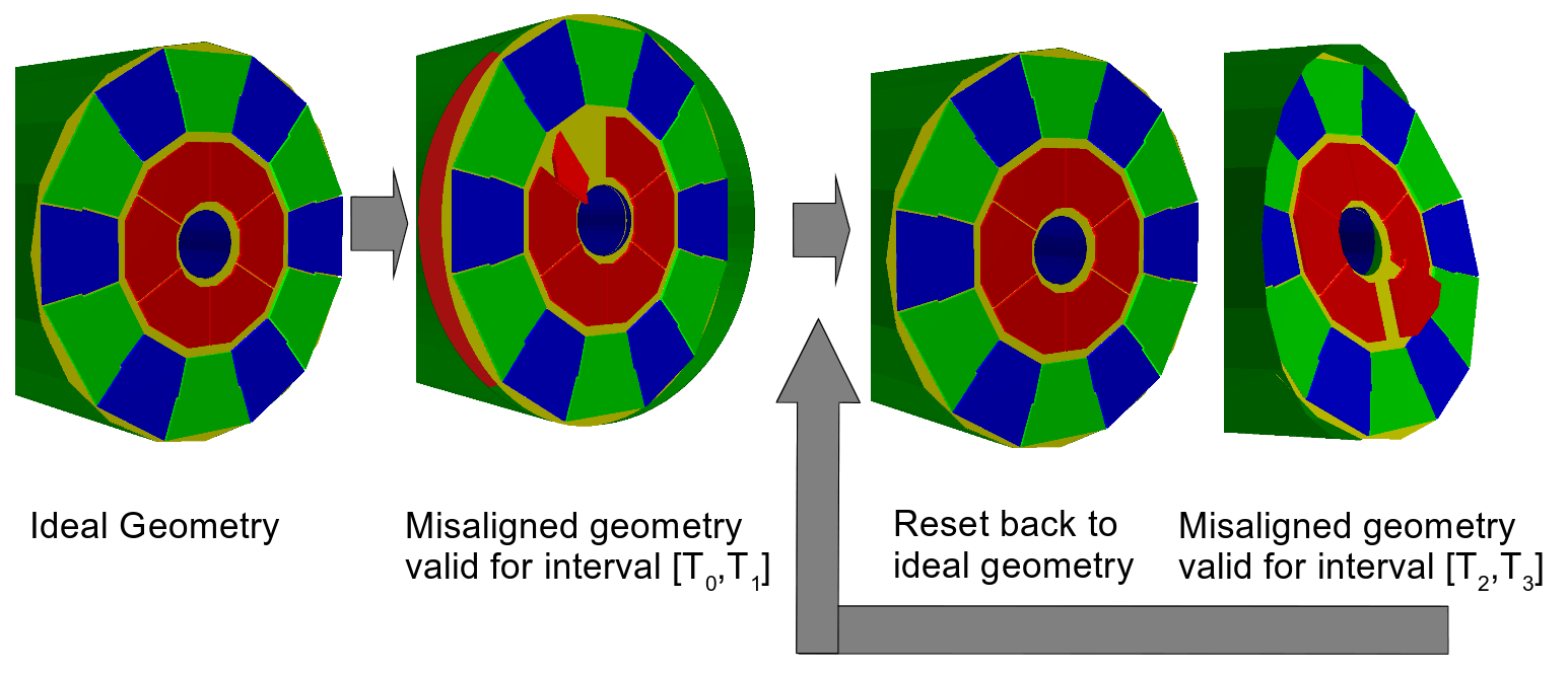
Technically it is possible to apply global alignment procedures iteratively. This however id deprecated and violates thread safety for the simple reason that the geometry in memory is altered. If applied, it is duty of the client framework to ensure that during the change of global alignment no processing of event data is ongoing. Hence, the procedure is described here only for completeness:
- Create the ideal detector using an ideal geometry.
- Apply a set of alignment parameters for a given time interval corresponding to the time a set of particle collisions were collected in the experiment.
- Process the set of collected particle collisions.
- Reset the misaligned detector to the ideal.
- Choose new event data input corresponding to another time interval and restart at item 2.
Graphically this use case is illustrated in Figure 4. In Section 5 the implementation to realize this use case is described.
2.3 Procedures to Determine Global Alignment Parameters
Typically the determination of alignment parameters requires a starting point which is not necessarily identical to the ideal position of a volume [3]. These volume positions are the result of a survey measurement or the result of internal position measurements of a sub-volume within a sub-detector e.g. on a measurement bench. In the following we call these parameters survey parameters. Survey parameters default to the ideal volume position if not supplied, alternatively, if set, to the provided position. Survey parameters are, like the alignment parameters, provided in terms of changes with respect to the ideal position and hence may be treated in a similar way.
The survey parameters are accessible to users through the interface offered by the objects.
2.4 Simulation of Non-Ideal Detector Geometries
It is a standard procedure in high energy physics to at least verify the measured detector response of a given physics process in particle collisions with the expected simulated detector response. For most purposes the simulation of an ideal detector is certainly is sufficient - though not describing the full truth. Sometimes however, the detector geometry must be simulated with a geometry as close to the known geometry as possible.
The simulation of such a geometry with applied alignment parameters can rather easily be realized using using the , DDAlign and the DDG4 frameworks:
-
The ideal geometry is constructed using the standard procedures of [1].
-
Then the alignment parameters are applied and finally
-
the corrected geometry is translated to [6] using the DDG4 [4] package. All particle collisions simulated with this translated geometry correspond to the modified geometry including the geometry modifications.
There is a caveat though: The application of alignment parameters can easily create volume overlaps, which are highly disliked by the runtime. If the above described procedure is applied, it is highly advised to check the resulting geometry for overlaps. Both, [5] and [6] offer tools to perform such tests.
To simulate distorted geometries clients should use the interface described in section 2.5.
2.5 The Global Alignment Interface
In this chapter will be documented how to use the interface of DDAlign . As already mentioned in section 1, this interface allows to alter the layout of the geometry in memory. Use cases are e.g. the simulation of non-ideal geometries.
Global alignment can be applied to detector elements using a specialized interface GlobalDetectorAlignment 2 . This interface provides the API to apply global changes to the geometry provided the presence of alignment parameters as shown in the following code snippet: /// First install the global alignment cache to build proper transactions Detector& detector = ...; GlobalAlignmentCache* cache = GlobalAlignmentCache::install(detector); /// Now create the transaction context. There may only be one context present GlobalAlignmentStack::create(); GlobalAlignmentStack& stack = GlobalAlignmentStack::get(); /// Now we can push any number of global alignment entries to the stack: DetElement elt = ...detector element containing the volume to be re-aligned ...; string placement = "/full/path/to/the/volume/to/be/realigned"; Alignments::Delta delta = ...; double ovl = allowed_overlap_in cm; // e.g. 0.001; // Create the new stack entry and insert it to the stack dd4hep_ptr<StackEntry> entry(new StackEntry(elt,placement,delta,ovl)); stack->insert(entry); /// Finally we commit the stacked entries and release the stack. cache->commit(stack); GlobalAlignmentStack::get().release();
Explanation:
| Line |
|
| 3 | Install the . Required to be done once. The object is registered to the instance and kept there. |
| 3-8 | The fact that the classes and are singletons is not a fundamental issue. However, we want to call the XML parser (or other database sources) iteratively and currently cannot chain a context (stack). |
| 16-21 | The created stacked entries are automatically released once the transaction is committed. |
Please note, that this interface normally is not directly invoked by users, but rather called by plugin mechanisms as the one described below capable of reading the global misalignments from XML.
2.5.1 Loading Global Geometrical Imperfections from XML
In this section we describe how to load global geometry imperfections and to apply them to an existing geometry. Loading the XML file is done automatically using the standard XML loader plugin provided by . This mechanism is favoured and much simpler than programming the global misalignment directly. This plugin is interfaced to the Detector instance and invoked from code as follows:
Detector& detector = ....; detector.fromXML("file:AlepTPC_alignment.xml");
To fully exploit the capabilities it is important to understand the interpreted structure of the XML file being processed. At the top level of the primary input file (i.e. the file given to the XML processor) the following structure is expected:
<global_alignment> <!-- Open the alignment transaction --> <open_transaction/> <subdetectors> <!-- Container with the list of subdetectors to be processed. --> <detelement path="TPC" reset="true" reset_children="true"> <!-- Move the entire TPC in the world volume --> <position="" x="30" y="30" z="80"/> <!-- Now add daughter detector elements --> <!-- Twist a bit the entire endcap by rotating it around the x and the y axis --> <detelement path="/world/TPC/TPC_SideA" check_overlaps="false"> <position x="0" y="0" z="0"/> <rotation x="-0.2" y="-0.2" z="0"/> <!-- Apply corrections of type Translation*Rotation to a single sector <detelement path="TPC_SideA_sector02" check_overlaps="true"> <position x="0" y="0" z="0"/> <rotation x="0.5" y="0.1" z="0.2"/> </detelement> </detelement> <!-- And the full shooting match of transformations for this sector --> <detelement path="TPC_SideA/TPC_SideA_sector03" check_overlaps="true"> <position x="0" y="0" z="290.0*mm"/> <rotation x="0" y="pi/2" z="0"/> <pivot x="0" y="0" z="100"/> </detelement> .... <!-- Include alignment files to be processed in the context of the "TPC" DetElement <include ref="file-name"/> </detElement> </subdetectors> <!-- Include alignment files to be processed at the top level context --> <include ref="file-name"/> <!-- Close the alignment transaction --> <close_transaction/> </global_alignment>
The structure of the alignment file explained quickly:
| Line |
|
| 1 | The root tag for the primary alignment file is <alignment/>. The primary tag name is mandatory and actually is used to invoke the correct interpreter. |
| 2,41 | Trigger the alignment transaction by specifying the transaction tags in the main XML file. |
| 4 | Definition of the set of subdetectors to be processed. A valid alias for this directive isdetelements. |
| 5 | The first subdetector: TPC. The subdetector tag is detelement Each detelement may recursively contain other detelement tags. as they were defined in the DetElement hierarchy. Internal detelement elements are processed in the context of the outer element i.e. paths may be specified relative to the parent or as absolute paths with respect to the world (starting with a ’/’). |
| 7 | Global movement of the TPC |
| 12-20 | Realignment entry for the TPC endcap A named TPC_SideA |
| 16-19 | Realignment entry for sector named TPC_SideA_sector02 of the TPC endcap A. Here the sector is specified directly as a daughter of the endcap. The name of the DetElement is relative to the parent. |
| 23-27 | Realignment entry for sector named TPC_SideA_sector03 of the TPC endcap A containing a full transformation: |
| 32 | Optionally detelement elements may include other alignment files specifying lower volume levels. These files are interpreted in the context of the calling detector element. |
| 38 | Optionally the subdetector alignment constants may be fragmented into several files, which can be loaded using the include directive. Each file could for example describe one single detector. |
The specification of any transformation element is optional:
-
The absence of a translation implies the origin (0,0,0)
-
The absence of a pivot point implies the origin (0,0,0)
-
The absence of a rotation implies the identity rotation. Any supplied pivot point in this case is ignored.
The absence of a transformation element is absolutely legal and does not issue any warning or error.
All transformations describe the change of placement with respect to the coordinate system of the closest mother-volume in the volume hierarchy, i.e. translations, rotations and pivot points are local to the mother coordinate system.
Included files may directly start with the root tags subdetectors, detelements or detelement and may recursively include other files. Except for the top level these files are processed in the calling context. The result of this procedure is shown in Figure 5.
2.5.2 Export Geometrical Imperfections to XML
In this section we describe how to export geometry imperfections to an XML file. A small helper class AlignmentWriter achieves this task as shown in the snippet:
Detector& detector = ....; DetElement top = detector.world(); if ( top.isValid() ) { AlignmentWriter wr(detector); return wr.write(top,output,enable\_transactions); }
This code will dump all alignment constants contained in the DetElement hierarchy of top to the output file output. The optional argument enable_transactions (default: true) will add the tags <open_transaction/> and <close_transaction/> to the output file. The output file conforms to the specifications described in Section ?? and may later be imported by another process.
FIXME: This chapter sort of still has to be written/completed!!!!