1 Introduction
This manual should introduce to the DDAlign framework. One goal of DDAlign is to easily model geometrical imperfections applied to the ideal geometry of detection devices as they are typically used in high energy physics experiments.
To avoid confusion within this document, a few terms need to be defined with respect to detector alignment:
-
The ideal geometry describes the detector as it was designed. Such a detector is an utopia, which can never be realized in terms of the placement of the individual components as such.
-
The actual geometry describes - as a first approximation to the real world - the real detector at a given time valid for a rather significant amount of time e.g. for a year of data taking. The actual geometry typically includes corrections deduced e.g. from optical surveys etc. The actual geometry does not change during the life-time of an analysis or calibration process. In the following this is called Global Alignment. The transformation of the ideal geometry to the actual geometry is steered by alignment parameters aka Alignment Deltas. Such deltas may be applied at any level of the geometrical hierarchy. In short, the actual geometry results from the ideal geometry after applying the global Alignment Deltas and is then the geometry in memory. The ROOT geometry toolkit is the only one, which allows for global alignment procedures 1.
-
Realignment then defines the procedures to correct data collected in particle collisions. These data are taken with the real, a priori unknown geometry, which on top of the actual geometry suffers from small shifts e.g. due to temperature or pressure changes. These shifts normally are frequently computed by specialized applications with respect to the to the actual geometry and typically are valid for relatively short time periods O(1 hour). These shifts, called Alignment Deltas, are used to re-align the detector response for physics analysis. This process in the following is called Local Alignment. The handling of the Alignment Deltas for local alignments in fact is very similar to the handling of detector conditions implemented in the package DDCond [7]. In section 4 this issue is further elaborated.
Technically the Alignment Deltas used for the global alignment and the Alignment Deltas used for the local alignment are identical. Though it should be stressed that the use is entirely different: Whereas the first actually alter the geometry, the latter are only used to properly interpret the data collected.
DDAlign formalizes both the access and the application of alignment parameters to the ideal geometry. The possibility to properly describe actual geometries with respect to ideal geometries is essential to understand the detector response to particle collisions and to connect response of geometrical independent areas of the experiment e.g. to one single track.
In this manual we will shortly describe the model used to describe an experiments detector description and then in more detail document the support for alignment with its programming interfaces.
1.1 Generic Detector Description Model
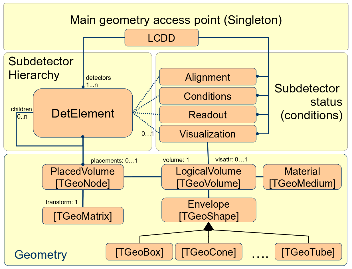
This is the heart of the DD4hep detector description toolkit. Its purpose is to build in memory a model of the detector including its geometrical aspects as well as structural and functional aspects. The design reuses the elements from the ROOT geometry package and extends them in case required functionality is not available. Figure 1 illustrates the main players and their relationships [1]. Any detector is modeled as a tree of , the entity central to this design, which is represented in the implementation by the class [2]. It offers all applications a natural entry point to any detector part of the experiment and represents a complete sub-detector (e.g. TPC), a part of a sub-detector (e.g. TPC-Endcap), a detector module or any other convenient detector device. The main purpose is to give access to the data associated to the detector device. For example, if the user writes some TPC reconstruction code, accessing the TPC detector element from this code will provide access the all TPC geometrical dimensions, the alignment and calibration constants and other slow varying conditions such as the gas pressure, end-plate temperatures etc. The acts as a data concentrator. Applications may access the full experiment geometry and all connected data through a singleton object of type , which provides management, bookkeeping and ownership to the model instances.
The geometry is implemented using the ROOT geometry classes, which are used directly without unnecessary interfaces to isolate the end-user from the actual ROOT based implementation. DDAlign allows client to access, manage and apply alignment parameters or smallish changes to the ideal geometry. The mechanism to achieve this is described in the following.

1.2 Detector Element Tree and the Geometry Hierarchy
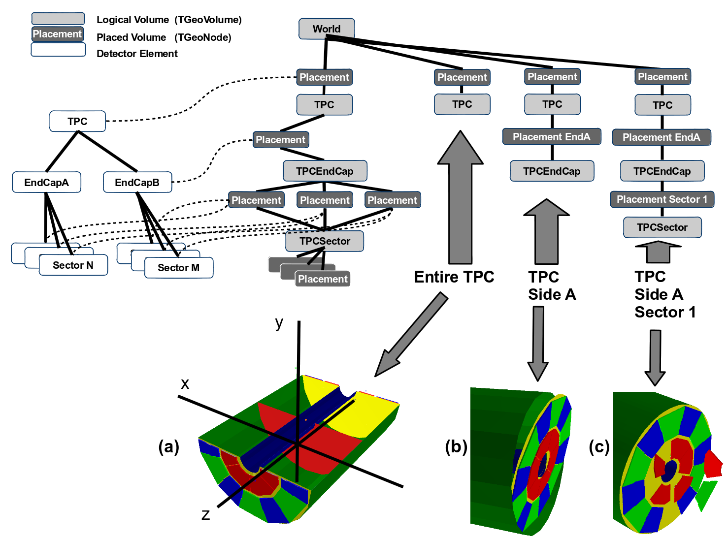
The geometry part of the detector description is delegated to the ROOT classes. are the basic objects used in building the geometrical hierarchy. A is a shape with its dimensions and consist of a given material. They represent unpositioned objects which store all information about the placement of possibly embedded volumes. The same volume can be replicated several times in the geometry. The also represents a system of reference with respect to its containing volumes. The reuse of instances of for different placements optimizes the memory consumption and detailed geometries for complex setups consisting of millions of volumes may be realized with reasonable amount of memory. The difficulty is to identify a given positioned volume in space and e.g. apply alignment parameters to one of these volumes. The relationship between the Detector Element and the placements is not defined by a single reference to the placement, but the full path from the top of the detector geometry model to resolve existing ambiguities due to the reuse of . Hence, individual volumes must be identified by their full path from mother to daughter starting from the top-level volume.
The tree structure of is a parallel structure to the geometrical hierarchy. This structure will probably not be as deep as the geometrical one since there would not need to associate detector information at very fine-grain level - it is unlikely that every little metallic screw needs associated detector information such as alignment, conditions, etc. Though this screw and many other replicas must be described in the geometry description since it may be important e.g. for its material contribution in the simulation application. Thus, the tree of Detector Elements is fully degenerate and each detector element object will be placed only once in the detector element tree as illustrated for a hypothetical Time Projection Chamber (TPC) detector in Figure 2 with an ideal geometry, where no positioning corrections are applied to neither child. It is essential to realize that the geometry tree in an ideal geometry is degenerate contrary to the tree of detector elements.
It should be noted, that alignment parameters may be applied to any volume of the ideal geometry. The alignment only affects the actual position of a volume it is e.g. irrelevant if the volume is sensitive or not.