2 Basics
This chapter describes how supply a physics application developed with all the information related to the detector which is necessary to process data from particle collisions and to qualify the detecting apparatus in order to interpret these event data.
The clients of the detector description are the algorithms residing in the event processing framework that need this information in order to perform their job (reconstruction, simulation, etc.). The detector description provided by DD4hep is a framework for developers to provide the specific detector information to software algorithms, which process data from particle collisions.
In the following sections an overview is given over the various independent elements of DD4hep followed by the discussion of an example which leads to the description of a detector when combining these elements. This includes a discussion of the features of the DD4hep detector description and of its structure.
2.1.1 Supported Platforms
2.1.2 Prerequisites
2.1.3 CMake Build Options for DD4hep
2.1.4 Build From Source
2.1.5 Remarks
2.1.6 Caveat
2.2 DD4hep Handles
2.3 The Data Extension Mechanism
2.4 XML Tools and Interfaces
2.5 The Detector Description Data Hub: Detector
2.6 Detector Description Persistency in XML
2.7 Units
2.7.1 Input data with units
2.7.2 Output data with units
2.7.3 Units in namespaces
2.8 Material Description
2.9 Shapes
2.9.1 Shape factories
2.10 Volumes and Placements
2.11 Detector Elements
2.12 Sensitive Detectors
2.13 Description of the Readout Structure
2.13.1 CellID Descriptors
2.13.2 Segmentations
2.13.3 Volume Manager
2.13.4 Static Electric and Magnetic Fields
2.14 Detector Constructors
2.15 Tools and Utilities
2.15.1 Geometry Visualization
2.15.2 Geometry Conversion
2.15.3 Overlap checking
2.15.4 Geometry checking
2.15.5 Directional Material Scans
2.15.6 Plugin Test Program
2.16 Standard Plugins
2.16.1 Geometry Display
2.16.2 Execute a Function in a Library
2.16.3 Start the ROOT Interpreter
2.16.4 Start the DD4hep UI
2.16.5 Dump GDML Tables of the TGeoManager
2.16.6 Dump Optical Surfaces of the TGeoManager
2.16.7 Dump Skin Surfaces of the TGeoManager
2.16.8 Dump Border Surfaces of the TGeoManager
2.16.9 Dump the Element/Material Table of the TGeoManager
2.16.10 Load and Interprete XML file
2.16.11 Load and Interprete XML Element
2.16.12 Load and Initialize the DD4hep Volume Manager
2.16.13 Dump Detector Description to ROOT file
2.16.14 Load Detector Description from ROOT file
2.16.15 Dump Geometry to ROOT file
2.16.16 Dump DetElement/Volume Tree
2.16.17 Fill DetElement Cache
2.17 Shape and Volume Plugins
2.17.1 Assembly Shape Construction
2.17.2 Scaled Shape Construction
2.17.3 Box Shape Construction
2.17.4 Half-Space Construction
2.17.5 Cone Construction
2.17.6 Polycone Construction
2.17.7 Cone Segment Construction
2.17.8 Tube Construction
2.17.9 Trap Construction
2.17.10 Regular Trapezoid (TRD1) Construction
2.17.11 Irregular Trapezoid (TRD2) Construction
2.17.12 Torus Shape Construction
2.17.13 Sphere Shape Construction
2.17.14 Paraboloid Shape Construction
2.17.15 Hyperboloid Shape Construction
2.17.16 Regular Polyhedron Construction
2.17.17 Irregular Polyhedron Construction
2.17.18 Eight-Point Solid Construction
2.17.19 Tessellated Solid Construction
2.17.20 Boolean Shape Construction
2.18 Readout Segmentation
2.1 Building DD4hep
2.1.2 Prerequisites
2.1.3 CMake Build Options for DD4hep
2.1.4 Build From Source
2.1.5 Remarks
2.1.6 Caveat
The DD4hep source code is freely available and is distributed under the GPLv3 License. See the doc/LICENSE in the repository [1] for more information. Please read the Release Notes before downloading or using this release.
The DD4hep project consists of several packages. The idea has been to separate the common parts of the detector description toolkit from concrete detector examples.
The package DDCore contains the definition of the basic classes of the toolkit: Handle, DetElement, Volume, PlacedVolume, Shapes, Material, etc. Most of these classes are handles to ROOT’s TGeom classes.
2.1.1 Supported Platforms
Actively supported and tested platforms for DD4hep are :
-
AlmaLinux 9
-
CERN CentOS 7
-
Apple macOS
Support for any other platform will well be taken into account, but can only be actively supported by users who submit the necessary patches.
2.1.2 Prerequisites
DD4hep depends on a number of external packages. The user will need to install these in his/her system before building and running the examples
-
CMake version 3.14 or higher
-
ROOT 6 installations.
-
Xerces-C if used to parse compact descriptions an installation of Xerces-C will is required.
-
To build DDG4 it is mandatory to have an installation of the Boost header files.
-
To build and run the simulation examples Geant4 will be required.
2.1.3 CMake Build Options for DD4hep
The package provides the basic mechanisms for constructing the Generic Detector Description Model in memory from XML compact detector definition files. Two methods are currently supported: one based on the C++ Xerces-C parser.
The XML parsing method is enabled by default using the TinyXML parser. Optionally instead of TinyXML the Xerces-C parser may be chosen by setting the two configuration options appropriately:
1    -DDD4HEP_USE_XERCESC=ON
2    -DXERCESC_ROOT_DIR=<path to Xerces-C-installation-directory>
DDG4 is the package that contains the conversion of DD4hep geometry into Geant4 geometry to be used for simulation. The option DD4HEP_WITH_GEANT4:BOOL controls the building or not of this package that has the dependency to Geant4. The Geant4 installation needs to be located using the variable:
1   -DDD4HEP_WITH_GEANT4=ON
2   -DGeant4_DIR=<path to Geant4Config.cmake>
To properly handle component properties using boost::spirit, access to the Boost header files must be provided.
1    -DBoost_INCLUDE_DIR=<path to the boost include directory>
2    -DBoost_NO_BOOST_CMAKE=ON  (to disable the search of boost-cmake)
To build only the doxygen documentation and user manuals without the need for any dependencies one can use the following command
1 cmake -DBUILD_DOCS_ONLY=ON ..
After one can execute the following target for building doxygen documentation
1make reference
and for building the user manuals
1make pdf
2.1.4 Build From Source
NEED REWRITE ONCE FINALIZED
2.1.5 Remarks
The main reference is the doxygen information of DD4hep and the ROOT documentation. Please refer to these sources for a detailed view of the capabilities of each component and/or its handle. For coherence reasons, the description of the interfaces is limited to examples which illustrate the usage of the basic components.
2.1.6 Caveat
NEEDS ADDITIONAL CLARIFICATION
2.2 DD4hep Handles
Handles are the means of clients accessing DD4hep detector description data. Handles are an intrinsic ingredient to DD4hep meant to also support various views onto relatively simple structures. The data itself is not held by the handle itself, the handle only allows the access to the data typically held by a pointer.
DD4hep internally prefers to expose data structures which are as simple as possible while at the same time being as complicated as necessary. These objects are then manipulated by Handles, smart pointer objects with sometimes specialized functionality depending on the contained data type. It is seen as a clear advantage that these smart pointer objects to not impose any restrictions on the underlying object except the accessibility of the contained data.
The freedom to attach handle based facades to virtually any data item allows for optimized data views depending on the application type, such as special views for reconstruction, simulation, tracking, etc.
For the importance of the functionality of this issue we repeat here the functionality described in 1.3.2 which is achieved by specializing the basic templated handle implementation:
- Convenience Views
-
provide higher level abstractions and internally group complex calculations. Such views simplify the life of the end-users.
- Optimization Views
-
allows end-users extend the data of the common detector detector element and store precomputed results, which would be expensive to obtain repeatedly.
- Compatibility Views
-
help to ensure smooth periods of software redesign. During the life-time of the experiment often various software constructs are for functional reasons re-designed and re-engineered. Compatibility Views either adapt new data designs to existing application code or expose new behavior based on existing data.
Since the lifetime of DD4hep objects is mostly defined by the lifetime of the dd4hep::Detector object (in turn defining the lifetime of ROOT’s TGeoManager) or for the conditions is managed by the ConditionsManager object under the steering of the embedding framework there is also no memory model imposed which would only lead to performance penalties. Hence, handles can be applied to data structures independent of their origin:
-
allocated from the stack
-
allocated from the heap
-
allocated as single objects of in bulk by array constructors.
There is no restriction to allow toolkit users to extend any of the internally used DD4hep classes such as e.g. the dd4hep::DetElement data object dd4hep::detail::DetElementObject with their own implementation supporting further enhanced functionality both in terms of additional data and additional member functions provided the user specialized class inherits from the DD4hep provided base. Obviously such enhancements do not hold for the geometry classes provided by ROOT because here the ROOT framework internally calls its object constructors. Hence, though DD4hep internally uses templated handles to manipulate data objects, DD4hep allows for all freedom to extend any of the internally used objects and a priori no restrictions are imposed by the DD4hep framework besides the mentioned inheritance.
The design approach of DD4hep to internally use handles to manipulate objects which is also offered to clients clearly has difficulties to support the Liskov substitution principle. This was a conscious decision when designing DD4hep.
Frameworks which see the substitution principle for the implementation of the simple data structures mandatory for its functionality clearly limit the benefits of the handles unless
-
the depending frameworks provides handles which are a fully implemented facade or
-
the depending framework use consistently the operator->() provided by all handles to directly access the underlying object or
-
the depending framework uses DD4hep and it is provided only internally and provide top level user code only with pointers/references to the data structures in their full object oriented glory.
The template handle class (see for details the Handle.h header file) allows type safe assignment of other unrelated handles and supports standard data conversions to the underlying object in form of the raw pointer, a reference etc. The template handle class:
1template <typename T> class Handle {
2public:
3  // Type definitions and class specific abbreviations and forward declarations
4  typedef T Implementation;
5  typedef Handle<Implementation> handle_t;
6public:
7  // Single and only data member: pointer to the underlying object
8  T* m_element;
9public:
10  Handle() : m_element(0) { }
11  Handle(T* e) : m_element(e) { }
12  Handle(const Handle<T>& e) : m_element(e.m_element) { }
13  template<typename Q> Handle(Q* e) : m_element((T*)e) { verifyObject(); }
14  template<typename Q> Handle(const Handle<Q>& e) : m_element((T*)e.m_element) { verifyObject(); }
15  Handle<T>& operator=(const Handle<T>& e) { m_element=e.m_element; return *this;}
16  bool isValid() const { return 0 != m_element; }
17  bool operator!() const { return 0 == m_element; }
18  void clear() { m_element = 0; }
19  T* operator->() const { return m_element; }
20  operator T& () const { return *m_element; }
21  T& operator*() const { return *m_element; }
22  T* ptr() const { return m_element; }
23  template <typename Q> Q* _ptr() const { return (Q*)m_element; }
24  template <typename Q> Q* data() const { return (Q*)m_element; }
25  template <typename Q> Q& object() const { return *(Q*)m_element; }
26  const char* name() const;
27};
effectively works like a pointer with additional object validation during assignment and construction. Handles support direct access to the held object: either by using the
operator->() (See line 19 above)
or the automatic type conversions:
      operator T& ()  const                (See line 20-21 above)
      T& operator*()  const
All entities of the DD4hep detector description are exposed as handles - raw pointers should not occur in the code. The handles to these objects serve two purposes:
-
Hold a pointer to the object and extend the functionality of a raw pointer.
-
Enable the creation of new objects using specialized constructors within sub-classes. To ensure memory integrity and avoid resource leaks these created objects should always be stored in the detector description data hub Detector described in section 2.5.
2.3 The Data Extension Mechanism
Data extensions are client defined C++ objects aggregated to basic DD4hep objects. The need to introduce such data extensions results from the simple fact that no data structure can be defined without the iterative need in the long term to extend it leading to implementations, which can only satisfy a subset of possible clients. To accomplish for this fact a mechanism was put in place which allows any user to attach any supplementary information provided the information is embedded in a polymorph object with an accessible destructor. There is one limitation though: object extension must differ by their interface type. There may not be two objects attached with the identical interface type. The actual implemented sub-type of the extension is not relevant. Separating the interface type from the implementation type keeps client code still functional even if the implementation of the extension changes or is a plug-able component.
The following code snippet shows the extension interface:
1  /// Extend the object with an arbitrary structure accessible by the type
2  template <typename IFACE, typename CONCRETE> IFACE* addExtension(CONCRETE* c);
3  /// Access extension element by the type
4  template <class T> T* extension() const;
Assuming a client class of the following structure:
1  class ExtensionInterface {
2    virtual ~ExtensionInterface();
3    virtual void foo() = 0;
4  };
5
6  class ExtensionImplementation : public ExtensionInterface {
7    ExtensionImplementation();
8    virtual ~ExtensionImplementation();
9  virtual void foo();
10  };
is then attached to an extensible object as follows:
1  ExtensionImplementation* ptr = new ExtensionImplementation();
2  /// ... fill the ExtensionImplementation instance with data ...
3  module.addExtension<ExtensionInterface>(ptr);
The data extension may then be retrieved whenever the instance of the extensible object “module” is accessible:
1 ExtensionInterface* ptr = module.extension<ExtensionInterface>();
The look-up mechanism is rather efficient. Though it is advisable to cache the pointer within the client code if the usage is very frequent.
There are currently three object types present which support this mechanism:
-
the central object of DD4hep, the Detector class discussed in section 2.5.
-
the object describing subdetectors or parts thereof, the DetElement class discussed in section 2.11. Detector element extensions in addition require the presence of a copy constructor to support e.g. reflection operations. Without a copy mechanism detector element hierarchies could cloned.
-
the object describing sensitive detectors, the SensitiveDetector class discussed in section 2.12.
2.4 XML Tools and Interfaces
Using native tools to interpret XML structures is rather tedious and lengthy. To easy the access to XML data considerable effort was put in place to easy the life of clients as much as possible using predefined instructs to access XML attributes, elements or element collections.
The functionality of the XML tools is perhaps best shown with a small example. Imagine to extract the data from an XML snippet like the following:
1  <detector name="Something">
2    <tubs rmin="BP_radius - BP_thickness" rmax="BP_radius" zhalf="Endcap_zmax/2.0"/>
3    <position x="0" y="0" z="Endcap_zmax/2.0" />
4    <rotation x="0.0" y="CrossingAngle/2.0" z="0.0" />
5    <layer id="1" inner_r="Barrel_r1" outer_r="Barrel_r1 + 0.02*cm" inner_z="Barrel_zmax + 0.1*cm">
6      <slice material = "G10" thickness ="0.5*cm"/>
7    </layer>
8    <layer id="2" inner_r="Barrel_r2" outer_r="Barrel_r2 + 0.02*cm" inner_z="Barrel_zmax + 0.1*cm">
9     <slice material = "G10" thickness ="0.5*cm"/>
10    </layer>
11    ....
12  </detector>
The variable names used in the XML snippet are evaluated when interpreted. Unless the attributes are accessed as strings, the client never sees the strings, but only the evaluated numbers. The anatomy of the C++ code snippets to interpret such a data section looks very similar:
1  static void some_xml_handler(xml_h e)  {
2    xml_det_t  x_det  (e);
3    xml_comp_t x_tube    = x_det.tubs();
4    xml_dim_t  pos       = x_det.position();
5    xml_dim_t  rot       = x_det.rotation();
6    string     name      = x_det.nameStr();
7
8    for(xml_coll_t i(x_det,_U(layer)); i; ++i)  {
9      xml_comp_t x_layer = i;
10      double  zmin = x_layer.inner_z();
11      double  rmin = x_layer.inner_r();
12      double  rmax = x_layer.outer_r();
13      double  layerWidh = 0;
14
15      for(xml_coll_t j(x_layer,_U(slice)); j; ++j)  {
16        double thickness = xml_comp_t(j).thickness();
17        layerWidth += thickness;
18      }
19    }
20  }
In the above code snippet an XML (sub-)tree is passed to the executing function as a handle to an XML element (xml_h). Such handles may seamlessly be assigned to any supporting helper class inheriting from the class XML::Element, which encapsulates the functionality required to interpret the XML structures. Effectively the various XML attributes and child nodes are accessed using functions with the same name from a convenience handle. In lines 3-5 child nodes are extracted, lines 10-12,16 access element attributes.Element collections with the same tag names layer and slice are exposed to the client code using an iteration mechanism.
Note the macros _U(layer) and _U(slice): When using Xerces-C as an XML parser, it will expand to the reference to an object containing the unicode value of the string “layer”. The full list of predefined tag names can be found in the include file XML/UnicodeValues.h. If a user tag is not part in the precompiled tag list, the corresponding Unicode string may be created with the macro _Unicode(layer) or the function Unicode(“layer”).
The convenience handles actually implement these functions to ease life. There is no magic - newly created attributes with new names obviously cannot be accessed with convenience mechanism. Hence, either you know what you are doing and you create your own convenience handlers or you restrict yourself a bit in the creativity of defining new attribute names.
There exist several utility classes to extract data from predefined XML tags:
-
Any XML element is described by an XML handle XML::Handle_t (xml_t). Handles are the basic structure for the support of higher level interfaces described above. The assignment of a handle to any of the interfaces below is possible.
-
The class XML::Element (xml_elt_t) supports in a simple way the navigation through the hierarchy of the XML tree accessing child nodes and attributes. Attributes at this level are named entities and the tag name must be supplied.
-
The class XML::Dimension with the type definition xml_dim_t, supports numerous access functions named identical to the XML attribute names. Such helper classes simplify the tedious string handling required by the
-
The class XML::Component (xml_comp_t) and the class XML::Detector (xml_det_t) resolving other issues useful to construct detectors.
-
Sequences of XML elements with an identical tag name may be handled as iterations as shown in the Figure above using the class XML::Collection_t.
-
Convenience classes, which allow easy access to element attributes may easily be constructed using the methods of the XML::Element class. This allows to construct very flexible thou non-intrusive extensions to DD4hep. Hence there is a priori no need to modify these helpers for the benefit of only one single client. In the presence of multiple requests such extensions may though be adopted.
It is clearly the responsibility of the client to only request attributes from an XML element, which exist. If an attribute, a child node etc. is not found within the element an exception is thrown.
The basic interface of the XML::Element class allows to access tags and child nodes not exposed by the convenience wrappers:
1  /// Access the tag name of this DOM element
2  std::string tag() const;
3  /// Access the tag name of this DOM element
4  const XmlChar* tagName() const;
5
6  /// Check for the existence of a named attribute
7  bool hasAttr(const XmlChar* name) const;
8  /// Retrieve a collection of all attributes of this DOM element
9  std::vector<Attribute> attributes() const;
10  /// Access single attribute by its name
11  Attribute getAttr(const XmlChar* name) const;
12  /// Access attribute with implicit return type conversion
13  template <class T> T attr(const XmlChar* tag) const;
14  /// Access attribute name (throws exception if not present)
15  const XmlChar* attr_name(const Attribute attr) const;
16  /// Access attribute value by the attribute  (throws exception if not present)
17  const XmlChar* attr_value(const Attribute attr) const;
18
19  /// Check the existence of a child with a given tag name
20  bool hasChild(const XmlChar* tag) const;
21  /// Access child by tag name. Thow an exception if required in case the child is not present
22  Handle_t child(const Strng_t& tag, bool except = true) const;
23  /// Add a new child to the DOM node
24  Handle_t addChild(const XmlChar* tag) const;
25  /// Check if a child with the required tag exists - if not create it and add it to the current node
26  Handle_t setChild(const XmlChar* tag) const;
2.5 The Detector Description Data Hub: Detector
As shown in Figure 1.2, any access to the detector description data is done using a standardized interface called Detector. During the configuration phase of the detector the interface is used to populate the internal data structures. Data structures present in the memory layout of the detector description may be retrieved by clients at any time using the Detector interface class. This includes of course, the access during the actual detector construction. The following code listing shows the accessor method to retrieve detector description entities from the interface. Not shown are access methods for groups of these entities and the methods to add objects:
1class Detector {
2  ///+++ Shortcuts to access often used quantities
3
4  /// Return handle to material describing air
5  virtual Material air() const = 0;
6  /// Return handle to material describing vacuum
7  virtual Material vacuum() const = 0;
8  /// Return handle to "invisible" visualization attributes
9  virtual VisAttr invisible() const = 0;
10
11  ///+++ Access to the top level detector elements and the corresponding volumes
12
13  /// Return reference to the top-most (world) detector element
14  virtual DetElement world() const = 0;
15  /// Return reference to detector element with all tracker devices.
16  virtual DetElement trackers() const = 0;
17
18  /// Return handle to the world volume containing everything
19  virtual Volume worldVolume() const = 0;
20  /// Return handle to the volume containing the tracking devices
21  virtual Volume trackingVolume() const = 0;
22
23  ///+++ Access to geometry and detector description objects
24
25  /// Retrieve a constant by its name from the detector description
26  virtual Constant constant(const std::string& name)      const = 0;
27  /// Retrieve a matrial by its name from the detector description
28  virtual Material material(const std::string& name)      const = 0;
29  /// Retrieve a field component by its name from the detector description
30  virtual DetElement detector(const std::string& name)      const = 0;
31  /// Retrieve a sensitive detector by its name from the detector description
32  virtual SensitiveDetector sensitiveDetector(const std::string& name) const = 0;
33  /// Retrieve a readout object by its name from the detector description
34  virtual Readout readout(const std::string& name)       const = 0;
35  /// Retrieve a id descriptor by its name from the detector description
36  virtual IDDescriptor idSpecification(const std::string& name)   const = 0;
37  /// Retrieve a subdetector element by its name from the detector description
38  virtual CartesianFieldfield(const std::string& name)     const = 0;
39
40  ///+++ Access to visualisation attributes and Geant4 processing hints
41
42  /// Retrieve a visualization attribute by its name from the detector description
43  virtual VisAttr visAttributes(const std::string& name) const = 0;
44
45  /// Retrieve a region object by its name from the detector description
46  virtual Region  region(const std::string& name)    const = 0;
47  /// Retrieve a limitset by its name from the detector description
48  virtual LimitSet limitSet(const std::string& name)      const = 0;
49  //...
50
51  ///+++ Extension mechanism:
52  /// Extend the sensitive detector element with an arbitrary structure accessible by the type
53  template <typename IFACE, typename CONCRETE> IFACE* addExtension(CONCRETE* c)
54};
As shown in the above listing, the Detector interface is the main access point to access a whole set
-
often used predefined values such as the material “air” or “vacuum” (line 5–10).
-
the top level objects “world”, “trackers” and the corresponding volumes (line 14–21).
-
items in the constants table containing named definitions also used during the interpretation of the XML content after parsing (line 26)
-
named items in the the material table (line 28)
-
named subdetectors after construction and the corresponding (line 30)
-
named sensitive detectors with their (line 32)
-
named readout structure definition using a (line 34)
-
named readout identifier descriptions (line 36)
-
named descriptors of electric and/or magnetic fields (line 39).
Additional support for specialized applications is provided by the interface:
-
Geant4: named region settings (line 46)
-
Geant4: named limits settings (line 48)
-
Visualization: named visualization attributes (line 43)
-
User defined extensions (line 53) are supported with the extension mechanism described in section 2.3.
All the values are populated either directly from XML or from detector constructors (see section 1.2.2). The interface also allows to load XML configuration files of any kind provided an appropriate interpretation plugin is present. In the next section we describe the functionality of the “lccd” plugin used to interpret the compact detector description. This mechanism can easily be extended using ROOT plugins, where the plugin name must correspond to the XML root element of the document to be interpreted.
2.6 Detector Description Persistency in XML
As explained in a previous section, the mechanism involved in the data loading allows an application to be fairly independent of the technology used to populate the transient detector representation. However, if one wants to use a given technology, she/he has to get/provide the corresponding conversion mechanism. The choice of XML was driven mainly by its easiness of use and the number of tools provided for its manipulation and parsing. Moreover, XML data can be easily translated into many other format using tools like XSLT processors. The grammar used for the XML data is pretty simple and straight forward, actually very similar to other geometry description languages based on XML. For example the material description is nearly identical to the material description in GDML [10]. The syntactic structure of the compact XML description was taken from the SiD detector description [9]. The following listing shows the basic layout of the compact detector description file with its different sections:
1<lccdd>
2  <info>   ...    </info>       Auxiliary detector model information
3  <includes>  ... </includes>   Section defining GDML files to be included
4  <define>  ...   </define>     Dictionary of constant expressions and variables
5  <materials> ... </materials>  Additional material definitions
6  <display>  ...  </display>    Definition of visualization attributes
7  <detectors> ... </detectors>  Section with sub-detector definitions
8  <readouts>  ... </readouts>   Section with readout structure definitions
9  <limits>  ...   </limits>     Definition of limit sets for Geant4
10  <fields>  ...   </fields>     Field definitions
11</lccdd>
The root tag of the XML tree is lccdd. This name is fixed. In the following the content of the various sections is discussed. The XML sections are filled with the following information:
-
The <info> sub-tree contains auxiliary information about the detector model:
1<info name="clic_sid_cdr"
2    title="CLIC Silicon Detector CDR"
3    author="Christian Grefe"
4    url="https://twiki.cern.ch/twiki/bin/view/CLIC/ClicSidCdr"
5    status="development"
6    version="$Id: compact.xml 665 2013-07-02 18:49:26Z markus.frank $">
7    <comment>The compact format for the CLIC Silicon Detector used
8                       for the conceptual design report</comment>
9</info>
-
The <includes> section allows to include GDML sub-trees containing material descriptions. These files are processed before the detector constructors are called:
1<includes>
2    <file  ref="elements.xml"/>
3    <file  ref="materials.xml"/>
4      ...
5</includes>
For historic reasons the tag <gdmlFile> is supported but deprecated in parallel with the new tag <file>.
-
The <define> section contains all variable definitions defined by the client to simplify the definition of subdetectors. These name-value pairs are fed to the expression evaluator and must evaluate by default to a number. The data type number is assumed by default (see example below). These number variables can be combined to formulas e.g. to automatically re-dimension subdetectors if boundaries are changed:
1<define>
2    <constant name="world_side" value="30000" type="number"/>
3    <constant name="world_x" value="world_side"/>
4    <constant name="world_y" value="world_side"/>
5    <constant name="world_z" value="world_side"/>
6    ....
7</define>
The other allowed data type is string. string values are stored in the raw format in the Detector object instance and can be retrieved by name. The values are as well added to the evaluation dictionary in order to resolve e.g. environment paths.
-
The <materials> sub-tree contains additional materials, which are not contained in the default materials tables. The snippet below shows an example to extend the table of known materials. For more details please see section 2.8.
1<materials>
2    <!-- The description of an atomic element or isotope -->
3    <element Z="30" formula="Zn" name="Zn" >
4        <atom type="A" unit="g/mol" value="65.3955" />
5    </element>
6    ...
7    <!-- The description of a new material               -->
8    <material name="CarbonFiber_15percent">
9        ...
10    </material>
11    ...
12</materials>
-
The visualization attributes are defined in the <display> section. Clients access visualization settings by name. The possible attributes are shown below and essentially contain the RGB color values, the visibility and the drawing style:
1<display>
2    <vis name="InvisibleNoDaughters"
3               showDaughters="false"
4               visible="false"/>
5    <vis name="SiVertexBarrelModuleVis"
6               alpha="1.0" r="1" g="1" b="0.6"
7               drawingStyle="solid"
8               showDaughters="true"
9               visible="true"/>
10    ....
11</display>
-
<limitsets> contain parameters passed to Geant4:
1<limits>
2        <limitset name="cal_limits">
3                 <limit name="step_length_max" particles="*" value="5.0" unit="mm" />
4        </limitset>
5</limits>
-
The detectors section contains subtrees of the type <detector> which contain all parameters used by the detector constructors to actually expand the geometrical structure. Each subdetector has a name and a type, where the type is used to call the proper constructor plugin. If the subdetector element is sensitive, a forward reference to the corresponding readout structure is mandatory. The remaining parameters are user defined:
1<detectors>
2    <detector id="4" name="SiTrackerEndcap" type="SiTrackerEndcap" readout="SiTrackerEndcapHits">
3        <comment>Outer Tracker Endcaps</comment>
4        <module name="Module1" vis="SiTrackerEndcapModuleVis">
5             <trd x1="36.112" x2="46.635" z="100.114/2" />
6             <module_component thickness="0.00052*cm"   material="Copper" />
7             <module_component thickness="0.03*cm"   material="Silicon" sensitive="true" />
8             ...
9        </module>
10        ...
11        <layer id="1">
12             <ring r="256.716" zstart="787.105+1.75" nmodules="24" dz="1.75" module="Module1"/>
13             <ring r="353.991" zstart="778.776+1.75" nmodules="32" dz="1.75" module="Module1"/>
14             <ring r="449.180" zstart="770.544+1.75" nmodules="40" dz="1.75" module="Module1"/>
15        </layer>
16        ...
17    </detector>
18</detectors>
-
The <readouts> section defined the encoding of sensitive volumes to so-called cell-ids, which are in DD4hep 64-bit integer numbers. The encoding is subdetector dependent with one exception: to uniquely identity each subdetector, the width of the system field must be the same.
1<readouts>
2    <readout name="SiTrackerEndcapHits">
3        <id>system:8,barrel:3,layer:4,module:14,sensor:2,side:32:-2,strip:20</id>
4    </readout>
5    ...
6</readouts>
-
Electromagnetic fields are described in the <fields> section. There may be several fields present. In DD4hep the resulting field vectors may be both electric and magnetic. The strength of the overall field is calculated as the superposition of the individual components:
1<fields>
2    <field name="GlobalSolenoid" type="solenoid"
3                   inner_field="5.0*tesla"
4                   outer_field="-1.5*tesla"
5                   zmax="SolenoidCoilOuterZ"
6                   outer_radius="SolenoidalFieldRadius">
7    </field>
8    ...
9</fields>
2.7 Units
DD4hep offers the user the possibility to choose and use the preferred units for any quantity and offers a consistent units solution defined as:
1static constexpr double centimeter = 1.;
2static constexpr double second = 1.;
3static constexpr double kiloelectronvolt = 1;
4static constexpr double eplus = 1.;
5static constexpr double kelvin = 1.;
6static constexpr double mole = 1.;
7static constexpr double candela = 1.;
8static constexpr double radian = 1.;
9static constexpr double steradian = 1.;
All other units are derived from the base ones:
1static constexpr double centimeter = 10. * millimeter;
2static constexpr double centimeter2 = centimeter * centimeter;
3static constexpr double centimeter3 = centimeter * centimeter * centimeter;
4
5static constexpr double meter = 1000. * millimeter;
6static constexpr double meter2 = meter * meter;
7static constexpr double meter3 = meter * meter * meter;
8
9static constexpr double kilometer = 1000. * meter;
10static constexpr double kilometer2 = kilometer * kilometer;
11static constexpr double kilometer3 = kilometer * kilometer * kilometer;
12
13static constexpr double kilogram = joule * second * second / (meter * meter);
One can find all units definitions in the file DDParsers/include/Evaluator/DD4hepUnits.h in the DD4hep source directory. All units are part of the dd4hep namespace. The reader might observe that the units convention is very close to the one used in ROOT/TGeo with the notable exception that in the latter case degree is set to 1 instead of radian.
2.7.1 Input data with units
The user must use units to define data which is to be used by DD4hep:
1double length = 5*dd4hep::cm;
2double time = 20*dd4hep::ns;
3double energy = 500*dd4hep::GeV;
DD4hep assumes that this convention for the units is respected, in order to assure independence. If units are not specified in the client application, data are implicitly treated in internal DD4hep units. This practice is however severely discouraged, as the base definition of units in DD4hep might change in a later version!
Be aware that DD4hep exposes to the user in many places underlying interfaces of Geant4, in such cases the user needs to use the Geant4/CLHEP system of units to interact.
2.7.2 Output data with units
When processing output data from DD4hep, it is imperative to cast the unit before forwarding the data to a third party program. To do so, it is sufficient to divide the data by the corresponding unit:
1cout << length / dd4hep::cm << " cm";
2cout << time / dd4hep::ns  << " ns";
3cout << energy / dd4hep::GeV  << " GeV";
DD4hep assumes that this convention for the units is respected, in order to assure independence. If units are not cast in the client application, DD4hep return values in internal units. This practice is however severely discouraged, as the base definition of units in DD4hep might change in a later version!
Be aware that DD4hep exposes to the user in many places underlying interfaces of Geant4, in such cases the user needs to divide the return value of such interface by the Geant4/CLHEP system of units:
1Geant4Calorimeter::Hit* hit;
2cout << hit->position.x() / CLHEP::mm << " mm";
Not casting the unit, and assuming implicit DD4hep units, would lead to a wrong result.
2.7.3 Units in namespaces
A very common scenario is that users need to handle in the same source code data from several different systems of units, like Geant4/CLHEP, DD4hep or others. DD4hep units are stored in the namespace dd4hep whilst Geant4/CLHEP units behavior depends on which units file the user includes:
-
G4SystemOfUnits.hh the units are directly in the top level namespace
-
CLHEP/Units/SystemOfUnits.h the units are inside the CLHEP:: namespace
It is imperative to keep in mind that for instance mm from DD4hepUnits.h takes precedence over mm from G4SystemOfUnits.hh inside the dd4hep namespace. The user is advised to always explicitly state which unit from which namespace is used. The following example code compiles without error:
1#include <G4SystemOfUnits.hh>
2namespace dd4hep {
3  Geant4Calorimeter::Hit* hit;
4  cout << hit->position.x() / mm << " mm";
5}
however it is logically wrong, as position will be cast to DD4hep mm instead of Geant4 mm. It is considered good practice to use CLHEP/Units/SystemOfUnits.h without using namespace CLHEP; and not rely at all on G4SystemOfUnits.hh whilst writing code that interacts with DD4hep.
2.8 Material Description
Materials are needed by logical volumes. They are defined as isotopes, elements or mixtures. Elements can optionally be composed of isotopes. Composition is always done by specifying the fraction of the mass. Mixtures can be composed of elements or other mixtures. For a mixture the user can specify composition either by number of atoms or by fraction of mass. The materials sub-tree in section 2.6 shows the representation of an element, a simple material and a composite material in the XML format identical to GDML [10]. The snippet below shows how to define new material instances:
1<materials>
2  ...
3  <!-- (1) The description of an atomic element or isotope -->
4  <element Z="30" formula="Zn" name="Zn" >
5    <atom type="A" unit="g/mol" value="65.3955" />
6  </element>
7  <!-- (2) A composite material                            -->
8  <material name="Kapton">
9    <D value="1.43" unit="g/cm3" />
10    <composite n="22" ref="C"/>
11    <composite n="10" ref="H" />
12    <composite n="2" ref="N" />
13    <composite n="5" ref="O" />
14  </material>
15  <!-- (3) A material mixture                              -->
16  <material name="PyrexGlass">
17    <D type="density" value="2.23" unit="g/cm3"/>
18    <fraction n="0.806" ref="SiliconOxide"/>
19    <fraction n="0.130" ref="BoronOxide"/>
20    <fraction n="0.040" ref="SodiumOxide"/>
21    <fraction n="0.023" ref="AluminumOxide"/>
22  </material>
23  ...
24</materials>
The <materials> sub-tree contains additional materials, which are not contained in the default materials tables. The snippet above shows different kinds of materials:
-
Atomic elements as they are in the periodic table. The number of elements is finite. It is unlikely any client will have to extend the known elements.
-
Composite materials, which consists of one or several elements forming a molecule. These materials have a certain density under normal conditions described in the child element D. For each composite the attribute ref denotes the element type by name, the attribute n denotes the atomic multiplicity. Typically each of the elements in (1) also forms such a material representing objects which consist of pure material like e.g. iron magnet yokes or copper wires.
-
Last there are mixtures of composite materials to describe for example alloys, solutions or other mixtures of solid materials. This is the type of material used to actually create mechanical structures forming the assembly of an experiment. Depending on the manufacturing these materials have a certain density (D) and are composed of numerous molecules contributing to the resulting material with a given fraction. The sum of all fractions (attribute n) is 1.0.
“Real” materials i.e. those you can actually touch are described in TGeo by the class TGeoMedium. 1. Materials are not constructed by any client. Materials and elements are either already present in the the corresponding tables of the ROOT geometry package or they are added during the interpretation of the XML input. Clients access the description of material using the Detector interface.
2.9 Shapes
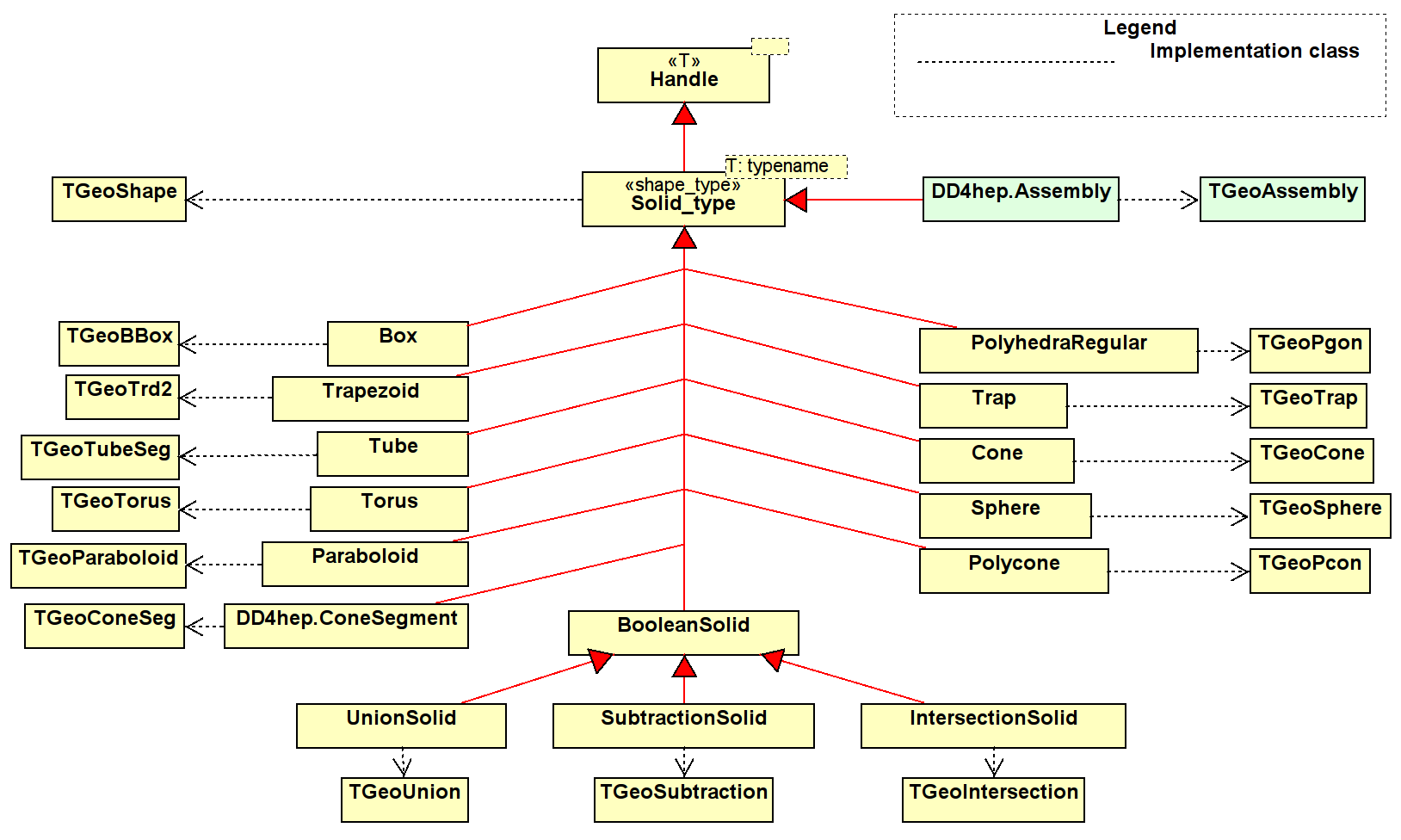
Shapes are abstract objects with a bounding surface and fixed dimensions. There are primitive, atomic shapes and complex boolean shapes as shown in Figure 2.1. The shapes have accessors for the most basic quantities to allow intrinsic access to the geometrical properties. Not all properties offered by TGeo are exposed. Other properties of the corresponding TGeo object can be accessed using the overloaded operator->() of the handle object. TGeo and similarly Geant4 offer a whole palette of primitive shapes, which can be used to construct more complex shapes:
-
Box shape represented by the TGeoBBox class. To create a new box object call one of the following constructors:
1/// Constructor to be used when creating an anonymous new box object
2Box(double x, double y, double z);
3/// Constructor to be used when creating an anonymous new box object
4template<typename X, typename Y, typename Z> Box(const X& x, const Y& y, const Z& z);
5
6/// Access half "length" of the box
7double x() const;
8/// Access half "width" of the box
9double y() const;
10/// Access half "depth" of the box
11double z() const;
-
Sphere shape represented by the TGeoSphere class. To create a new sphere object call one of the following constructors:
1/// Constructor to create a new anonymous object with attribute initialization
2Sphere(double rmin,            double rmax,
3               double startTheta= 0.0, double endTheta = M_PI,
4               double startPhi  = 0.0, double endPhi   = 2. * M_PI);
5/// Constructor to create a new identified object with attribute initialization
6Sphere(const std::string& nam, double rmin,            double rmax,
7               double startTheta= 0.0, double endTheta = M_PI,
8               double startPhi  = 0.0, double endPhi   = 2. * M_PI);
9
10/// Accessor: start-phi value
11double startPhi() const;
12/// Accessor: end-phi value
13double endPhi() const;
14/// Accessor: start-theta value
15double startTheta() const;
16/// Accessor: end-theta value
17double endTheta() const;
18/// Accessor: r-min value
19double rMin() const;
20/// Accessor: r-max value
21double rMax() const;
-
Cone shape represented by the TGeoCone class. To create a new cone object call one of the following constructors:
1/// Constructor to create a new anonymous object with attribute initialization
2Cone(double z,double rmin1,double rmax1,double rmin2,double rmax2);
3template<typename Z, typename RMIN1, typename RMAX1, typename RMIN2, typename RMAX2>
4Cone(const Z& z, const RMIN1& rmin1, const RMAX1& rmax1, const RMIN2& rmin2, const RMAX2& rmax2);
5
6/// Accessor: delta-z value
7double dZ() const;
8/// Accessor: r-min-1 value
9double rMin1() const;
10/// Accessor: r-min-2 value
11double rMin2() const;
12/// Accessor: r-max-1 value
13double rMax1() const;
14/// Accessor: r-max-2 value
15double rMax2() const;
-
ConeSegment shape represented by the TGeoConeSeg class. To create a new cone segment object call one of the following constructors:
1/// Constructor to create a new ConeSegment
2ConeSegment(double dz, double rmin1, double rmax1, double rmin2, double rmax2, double phi1=0.0, double phi2=2.0*M_PI);
3/// Constructor to create a new named ConeSegment object
4ConeSegment(const std::string& nam, double dz, double rmin1, double rmax1,
5                         double rmin2, double rmax2, double startPhi = 0.0, double endPhi = 2.0 * M_PI);
6
7/// Accessor: start-phi value
8double startPhi() const;
9/// Accessor: end-phi value
10double endPhi() const;
11/// Accessor: delta-z value
12double dZ() const;
13/// Accessor: r-min-1 value
14double rMin1() const;
15/// Accessor: r-min-2 value
16double rMin2() const;
17/// Accessor: r-max-1 value
18double rMax1() const;
19/// Accessor: r-max-2 value
20double rMax2() const;
-
Polycone shape represented by the TGeoPcon class. To create a new polycone object call one of the following constructors:
1/// Constructor to create a new polycone object
2Polycone(double start, double delta);
3followed by a call to:
4void addZPlanes(const std::vector<double>& rmin,
5                                  const std::vector<double>& rmax,
6                                  const std::vector<double>& z);
7/// Constructor to create a new polycone object. Add at the same time all Z planes
8Polycone(double start, double delta,
9                   const std::vector<double>& rmin,
10                   const std::vector<double>& rmax,
11                   const std::vector<double>& z);
12
13/// Accessor: start-phi value
14double startPhi() const;
15/// Accessor: delta-phi value
16double deltaPhi() const;
17/// Accessor: z value
18double z(int which) const;
19/// Accessor: r-min value
20double rMin(int which) const;
21/// Accessor: r-max value
22double rMax(int which) const;
23/// Accessor: vector of z-values for Z-planes value
24std::vector<double> zPlaneZ() const;
25/// Accessor: vector of rMin-values for Z-planes value
26std::vector<double> zPlaneRmin() const;
27/// Accessor: vector of rMax-values for Z-planes value
28std::vector<double> zPlaneRmax() const;
-
TubeSegment shape represented by the TGeoTubeSeg class. To create a new tube segment object call one of the following constructors:
1Tube(double rmin, double rmax, double z, double endPhi=2*M_PI)
2Tube(double rmin, double rmax, double z, double startPhi, double endPhi)
3
4template<typename RMIN, typename RMAX, typename Z, typename ENDPHI>
5Tube(const RMIN& rmin, const RMAX& rmax, const Z& z, const ENDPHI& endPhi)
6
7template<typename RMIN, typename RMAX, typename Z, typename STARTPHI, typename ENDPHI>
8Tube(const std::string& name, const RMIN& rmin, const RMAX& rmax, const Z& z,
9          const STARTPHI& startPhi, const ENDPHI& endPhi)
10
11/// Accessor: start-phi value
12double startPhi() const;
13/// Accessor: end-phi value
14double endPhi() const;
15/// Accessor: delta-z value
16double dZ() const;
17/// Accessor: r-min value
18double rMin() const;
19/// Accessor: r-max value
20double rMax() const;
-
CutTube shape represented by the TGeoCtub class. To create a new cut tube segment object call one of the following constructors:
1/// Constructor to create a new cut-tube object with attribute initialization
2CutTube(double rmin, double rmax, double dz, double startPhi, double endPhi,
3                 double lx, double ly, double lz, double tx, double ty, double tz);
4/// Constructor to create a new identifiable cut-tube object with attribute initialization
5CutTube(const std::string& name,
6                 double rmin, double rmax, double dz, double startPhi, double endPhi,
7                 double lx, double ly, double lz, double tx, double ty, double tz);
8
9/// Accessor: start-phi value
10double startPhi() const;
11/// Accessor: end-phi value
12double endPhi() const;
13/// Accessor: delta-z value
14double dZ() const;
15/// Accessor: r-min value
16double rMin() const;
17/// Accessor: r-max value
18double rMax() const;
19/// Accessor: lower normal vector of cut plane
20std::vector<double> lowNormal()  const;
21/// Accessor: upper normal vector of cut plane
22std::vector<double> highNormal() const;
-
EllipticalTube shape represented by the TGeoEltu class. To create a new elliptical tube segment object call one of the following constructors:
1/// Constructor to create a new anonymous tube object with attribute initialization
2EllipticalTube(double a, double b, double dz);
3/// Constructor to create a new identified tube object with attribute initialization
4EllipticalTube(const std::string& nam, double a, double b, double dz);
5
6/// Accessor: delta-z value
7double dZ() const;
8/// Accessor: a value (semi axis along x)
9double a() const;
10/// Accessor: b value (semi axis along y)
11double b() const;
-
Trapezoid shape represented by the TGeoTrd2 class. To create a new trapezoid object call one of the following constructors:
1/// Constructor to create a new anonymous object with attribute initialization
2Trapezoid(double x1, double x2, double y1, double y2, double z);
3/// Constructor to create a new anonymous object with attribute initialization
4template <typename X1,typename X2,typename Y1,typename Y2,typename Z>
5Trd2(X1 x1, X2 x2, Y1 y1, Y2 y2, Z z);
6/// Constructor to create a new identified object with attribute initialization
7Trd2(const std::string& nam, double x1, double x2, double y1, double y2, double z);
8/// Constructor to create a new identified object with attribute initialization
9template <typename X1,typename X2,typename Y1,typename Y2,typename Z>
10Trd2(const std::string& nam, X1 x1, X2 x2, Y1 y1, Y2 y2, Z z);
11
12/// Accessor: delta-x1 value
13double dX1() const;
14/// Accessor: delta-x2 value
15double dX2() const;
16/// Accessor: delta-y1 value
17double dY1() const;
18/// Accessor: delta-y2 value
19double dY2() const;
20/// Accessor: delta-z value
21double dZ() const;
-
Trap shape represented by the TGeoTrap class. To create a new trap object call one of the following constructors:
1/// Constructor to create a new anonymous object with attribute initialization
2Trap(double z,double theta,double phi,
3          double y1,double x1,double x2,double alpha1,
4          double y2,double x3,double x4,double alpha2);
5/// Constructor to create a new anonymous object for right angular wedge from STEP (Se G4 manual for details)
6Trap( double pz, double py, double px, double pLTX);
7
8/// Accessor: phi value
9double phi() const;
10/// Accessor: theta value
11double theta() const;
12/// Angle between centers of x edges and y axis at low z
13double alpha1()  const;
14/// Angle between centers of x edges and y axis at low z
15double alpha2()  const;
16/// Half length in x at low z and y low edge
17double bottomLow1()  const;
18/// Half length in x at high z and y low edge
19double bottomLow2()  const;
20/// Half length in x at low z and y high edge
21double topLow1()  const;
22/// Half length in x at high z and y high edge
23double topLow2()  const;
24/// Half length in y at low z
25double high1()  const;
26/// Half length in y at high z
27double high2()  const;
28/// Half length in dZ
29double dZ()  const;
-
Torus shape represented by the TGeoTorus class. To create a new torus object call one of the following constructors:
1/// Constructor to create a new anonymous object with attribute initialization
2Torus(double r, double rmin, double rmax, double phi=M_PI, double delta_phi=2.*M_PI);
3
4/// Accessor: start-phi value
5double startPhi() const;
6/// Accessor: delta-phi value
7double deltaPhi() const;
8
9/// Accessor: r value (torus axial radius)
10double r() const;
11/// Accessor: r-min value (inner radius)
12double rMin() const;
13/// Accessor: r-max value (outer radius)
14double rMax() const;
-
Paraboloid shape represented by the TGeoParaboloid class. To create a new paraboloid object call one of the following constructors:
1/// Constructor to create a new anonymous object with attribute initialization
2Paraboloid(double r_low, double r_high, double delta_z);
3
4/// Accessor: delta-z value
5double dZ() const;
6/// Accessor: r-min value
7double rLow() const;
8/// Accessor: r-max value
9double rHigh() const;
-
Hyperboloid shape represented by the TGeoHype class. To create a new hyperboloid object call one of the following constructors:
1/// Constructor to create a new anonymous object with attribute initialization
2Hyperboloid(double rin, double stin, double rout, double stout, double dz);
3/// Constructor to create a new identified object with attribute initialization
4Hyperboloid(const std::string& nam, double rin, double stin, double rout, double stout, double dz);
5
6/// Accessor: delta-z value
7double dZ() const;
8/// Accessor: r-min value
9double rMin() const;
10/// Accessor: r-max value
11double rMax() const;
12/// Stereo angle for inner surface
13double stereoInner()  const;
14/// Stereo angle for outer surface
15double stereoOuter()  const;
-
PolyhedraRegular shape represented by the TGeoPgon class. To create a new polyhedron object call one of the following constructors:
1/// Constructor to create a new object. Phi(start)=0, deltaPhi=2PI, Z-planes at +-zlen/2
2PolyhedraRegular(int nsides, double rmin, double rmax, double zlen);
3/// Constructor to create a new object. Phi(start)=0, deltaPhi=2PI, Z-planes at zplanes[0],[1]
4PolyhedraRegular(int nsides, double rmin, double rmax, double zplanes[2]);
5/// Constructor to create a new object with phi_start, deltaPhi=2PI, Z-planes at +-zlen/2
6PolyhedraRegular(int nsides, double phi_start, double rmin, double rmax, double zlen);
7
8/// Accessor: Number of edges
9int numEdges()  const;
10/// Accessor: start-phi value
11double startPhi() const;
12/// Accessor: delta-phi value
13double deltaPhi() const;
14
15/// Accessor: r-min value
16double z(int which) const;
17/// Accessor: r-min value
18double rMin(int which) const;
19/// Accessor: r-max value
20double rMax(int which) const;
21
22/// Accessor: vector of z-values for Z-planes value
23std::vector<double> zPlaneZ() const;
24/// Accessor: vector of rMin-values for Z-planes value
25std::vector<double> zPlaneRmin() const;
26/// Accessor: vector of rMax-values for Z-planes value
27std::vector<double> zPlaneRmax() const;
-
Polyhedra shape represented by the TGeoPgon class. To create a new generic polyhedron object call one of the following constructors:
1/// Constructor to create a new object. Phi(start), deltaPhi, Z-planes at specified positions
2Polyhedra(int nsides, double start, double delta, const std::vector<double>& z, const std::vector<double>& r);
3/// Constructor to create a new object. Phi(start), deltaPhi, Z-planes at specified positions
4Polyhedra(int nsides, double start, double delta,
5                     const std::vector<double>& z, const std::vector<double>& rmin, const std::vector<double>& rmax)
6
7/// Accessor: Number of edges
8int numEdges()  const;
9/// Accessor: start-phi value
10double startPhi() const;
11/// Accessor: delta-phi value
12double deltaPhi() const;
13
14/// Accessor: z value
15double z(int which) const;
16/// Accessor: r-min value
17double rMin(int which) const;
18/// Accessor: r-max value
19double rMax(int which) const;
20
21/// Accessor: vector of z-values for Z-planes value
22std::vector<double> zPlaneZ() const;
23/// Accessor: vector of rMin-values for Z-planes value
24std::vector<double> zPlaneRmin() const;
25/// Accessor: vector of rMax-values for Z-planes value
26std::vector<double> zPlaneRmax() const;
-
ExtrudedPolygon shape represented by the TGeoXtru class. To create a new extruded polygon object call one of the following constructors:
1/// Constructor to create a new object.
2ExtrudedPolygon(const std::vector<double> & pt_x,  const std::vector<double> & pt_y,
3                                  const std::vector<double> & sec_z, const std::vector<double> & sec_x, const std::vector<double> & sec_y,
4                                  const std::vector<double> & zscale);
5/// Constructor to create a new identified object.
6ExtrudedPolygon(const std::string& nam,
7                                  const std::vector<double> & pt_x,  const std::vector<double> & pt_y,
8                                  const std::vector<double> & sec_z, const std::vector<double> & sec_x, const std::vector<double> & sec_y,
9                                  const std::vector<double> & zscale);
10
11/// Access vector of x parameters of the various vertices
12std::vector<double> x() const;
13/// Access vector of x parameters of the various vertices
14std::vector<double> y() const;
15/// Access vector of z-values of the z plane parameters
16std::vector<double> z() const;
17/// Access vector of x-offsets of the z plane parameters
18std::vector<double> zx() const;
19/// Access vector of y-offsets of the z plane parameters
20std::vector<double> zy() const;
21/// Access vector of z-scale parameters
22std::vector<double> zscale() const;
-
EightPointSolid shape represented by the TGeoArb8 class. To create a generic solid defined by eight vertices call one of the following constructors:
1/// Constructor to create a new anonymous object with attribute initialization
2EightPointSolid(double dz, const double* vertices);
3/// Constructor to create a new identified object with attribute initialization
4EightPointSolid(const std::string& nam, double dz, const double* vertices);
5
6/// Accessor: delta-z value
7double dZ() const;
8/// Accessor: all vertices as STL vector
9std::vector<double> vertices() const;
10/// Accessor: single vertex
11std::pair<double, double> vertex(int which) const;
-
TessellatedSolid shape represented by the TGeoTessellated class. To create a generic solid defined by eight vertices call one of the following constructors:
1/// Constructor to create a new anonymous object with attribute initialization
2TessellatedSolid(int num_facets);
3/// Constructor to create a new identified object with attribute initialization
4TessellatedSolid(const std::vector<Vertex_t>& vertices);
5/// Constructor to create a new anonymous object with attribute initialization
6TessellatedSolid(const std::string& nam, int num_facets);
7/// Constructor to create a new identified object with attribute initialization
8TessellatedSolid(const std::string& nam, const std::vector<Vertex_t>& vertices);
9
10/// Add new facet to the shape
11bool addFacet(const Vertex_t& pt0, const Vertex_t& pt1, const Vertex_t& pt2)  const;
12/// Add new facet to the shape
13bool addFacet(const Vertex_t& pt0, const Vertex_t& pt1, const Vertex_t& pt2, const Vertex_t& pt3)  const;
14/// Add new facet to the shape. Call only if the tessellated shape was constructed with vertices
15bool addFacet(const int pt0, const int pt1, const int pt2)  const;
16/// Add new facet to the shape. Call only if the tessellated shape was constructed with vertices
17bool addFacet(const int pt0, const int pt1, const int pt2, const int pt3)  const;
Tessellated shapes play an essential role to support reading Computer Aided Design files in DD4hep. Such support is implemented in the DD4hep subpackage DDCAD.
Besides the primitive shapes three types of boolean shapes (described in TGeo by the TGeoCompositeShape class) are supported:
-
UnionSolid objects representing the union,
-
IntersectionSolid objects representing the intersection,
-
SubtractionSolid objects representing the subtraction,
of two other primitive or complex shapes. To build a boolean shape, the second shape is transformed in 3-dimensional space before the boolean operation is applied. The 3D transformations are described by objects from the ROOT::Math library and are supplied at construction time. Such a transformation as shown in the code snippet below may be
-
The identity transformation. Then no transformation object needs to be provided (see line 2).
-
A translation only described by a Position object (see line 4)
-
A 3-fold rotation first around the Z-axis, then around the Y-axis and finally around the X-axis. For transformation operations of this kind a RotationZYX object must be supplied (see line 6).
-
A generic 3D rotation matrix should be applied to the second shape. Then a Rotation3D object must be supplied (see line 8).
-
Finally a generic 3D transformation (translation+rotation) may be applied using a Transform3D object (see line 10).
All three boolean shapes have constructors as shown here for the UnionSolid:
1  /// Constructor to create a new object. Position is identity, Rotation is identity-rotation!
2  UnionSolid(const Solid& shape1, const Solid& shape2);
3  /// Constructor to create a new object. Placement by position, Rotation is identity-rotation!
4  UnionSolid(const Solid& shape1, const Solid& shape2, const Position& pos);
5  /// Constructor to create a new object. Placement by a RotationZYX within the mother
6  UnionSolid(const Solid& shape1, const Solid& shape2, const RotationZYX& rot);
7  /// Constructor to create a new object. Placement by a generic rotation within the mother
8  UnionSolid(const Solid& shape1, const Solid& shape2, const Rotation3D& rot);
9  /// Constructor to create a new object. Placement by a generic transformation within the mother
10  UnionSolid(const Solid& shape1, const Solid& shape2, const Transform3D& pos);
2.9.1 Shape factories
Sometimes it is useful to create shapes in an “abstract” way e.g. to define areas in the detector. To create such shapes a factory method was implemented, which allows to create a valid shape handle given a valid XML element providing the required attributes. The factory methods are invoked using from XML elements of the following form:
1 <some_element type="shape-type" .... args ....>
The shape is then constructed using the XML component object:
1#include "XML/Helper.h"
2
3xml_h e = <shape-element>;
4Box box = xml_comp_t(e).createShape();
5if ( !box.isValid() ) { /* ...handle error ... */  }
The required arguments for the various shapes are then:
-
For a Box:
1 <some_element type="Box" x="x-value" y="y-value" z="z-value"/>
fulfilling a constructor of the type: Box(dim.dx(), dim.dy(), dim.dz()).
-
For a Sphere the following constructor must be fulfilled:
1 Sphere(e.rmin(0), e.rmax(), e.starttheta(0), e.endtheta(), e.startphi(0), e.endphi());
The corresponding XML snippet looks like this:
1 <some_element type="Sphere" rmin="value" rmax="value" starttheta="value" endtheta="value" startphi="value" endphi="value"/>
where the above default values for the XML attributes rmin=0, starttheta=0, endtheta=, startphi=0, endphi=.
-
For a Cone the following constructor must be fulfilled:
1    double rmi1 = e.rmin1(0), rma1 = e.rmax1();
2    Cone(e.z(0), rmi1, rma1, e.rmin2(rmi1), e.rmax2(rma1));
The corresponding XML snippet looks like this:
1 <some_element type="Cone" z="value" rmin1="value" rmax1="value" rmin2="value" rmax2="value"/>
where the above default values for the XML attributes rmin1=0, rmin2=rmin1, rmax2=rmax1.
-
For a ConeSegment the following constructor must be fulfilled:
1ConeSegment(e.dz(), e.rmin1(0), e.rmax1(), e.rmin2(), e.rmax2(), e.startphi(), e.deltaphi())
where the above default values for the XML attributes rmin1=0, rmin2=0, rmax2=rmax1, startphi=0 and deltaphi= are used if not explicitly stated in the XML element e. The corresponding XML snippet looks like this:
1 <some_element type="ConeSegment" rmin1="value" rmax="value" rmin2="value" rmax2="value" dz="value" startphi="value" deltaphi="value"/>
-
For a Polycone:
1    <some_element type="Polycone" start="start-phi-value" deltaphi="delta-phi-value">
2        <zplane z="z-value" rmin="rmin-value" rmax="rmax-value"/>
3        <zplane z="z-value" rmin="rmin-value" rmax="rmax-value"/>
4        .... any number of Z-planes ....
5        <zplane z="z-value" rmin="rmin-value" rmax="rmax-value"/>
6    </some_element>
where the above default values for the XML attributes startphi=0 and deltaphi= and for each of the the z-planes rmin=0 are used if not explicitly stated in the XML element e.
-
For a Tube the constructor is:
1Tube(e.rmin(0.0), e.rmax(), e.dz(), e.startphi(), e.deltaphi())
The corresponding XML snippet looks like this:
1 <some_element type="Tube" rmin="value" rmax="value" dz="value" startphi="value" deltaphi="value"/>
where the defaults are rmin=0, startphi=0 and deltaphi=.
-
For a CutTube the constructor is:
1CutTube(e.rmin(0.0), e.rmax(), e.dz(), e.phi1(), e.phi2(), e.lx(), e.ly(), e.lz(), e.tx(), e.ty(), e.tz())
The corresponding XML snippet looks like this:
1    <some_element type="CutTube" rmin="value" rmax="value" dz="value" phi1="value" phi2="value"
2                                  lx="value" ly="value" lz="value" tx="value" ty="value" tz="value"/>
where the defaults are rmin=0.
-
For a EllipticalTube the constructor is:
1EllipticalTube(e.a(),e.b(),e.dz());
The corresponding XML snippet looks like this:
1 <some_element type="EllipticalTube" dz="value" a="value" b="value"/>
-
For a Trap the constructor is: if dz is specified:
1Trap(e.dz(), e.dy(), e.dx(),_toDouble(_Unicode(pLTX)))
Alternatively, if the tag dz is not present:
1Trap(e.z(0.0), e.theta(), e.phi(0), e.y1(), e.x1(), e.x2(), e.alpha1(), e.y2(), e.x3(), e.x4(), e.alpha2())
The corresponding XML snippet looks like this:
1    <some_element type="Trap" z="value" theta="value" phi="value"
2                                                           y1="value" x1="value" x2="value" alpha1="value"
3                                                           y2="value" x3="value" x4="value" alpha2="value"/>
Defaults are: theta=0, phi=0, alpha1=0, alpha2=0
-
For a Trapezoid the constructor is:
1Trapezoid(e.x1(), e.x2(), e.y(), e.z(0))
The corresponding XML snippet looks like this:
1 <some_element type="Trapezoid" x1="value" x2="value" y="value" z="value"/>
The Trapezoid is also aliased to Trd2.
-
For a simplified Trapezoid, the Trd1 the constructor is:
1Trd1(e.x1(), e.x2(), e.y1(), e.y2(), e.z(0));
The corresponding XML snippet looks like this:
1 <some_element type="Trd1" x1="value" x2="value" y1="value" y2="value" z="value"/>
-
For a Torus the constructor is:
1Torus(e.r(), e.rmin(), e.rmax(), e.startphi(), e.deltaphi())
The corresponding XML snippet looks like this:
1 <some_element type="Torus" r="value" rmin="value" rmax="value" startphi="value" deltaphi="value"/>
Defaults are: rmin=0, startphi=, deltaphi=.
-
For a Sphere the constructor is:
1Sphere(e.rmin(), e.rmax(), e.starttheta(), e.deltatheta(), e.startphi(), e.deltaphi())
The corresponding XML snippet looks like this:
1    <some_element type="Sphere" rmin="value" rmax="value"
2                                  starttheta="value" deltatheta="value" startphi="value" deltaphi="value"/>
Defaults are: rmin=0, starttheta=0, deltatheta=, startphi=0, deltaphi=.
-
For a Paraboloid the constructor is:
1Paraboloid(e.rmin(0), e.rmax(), e.dz())
The corresponding XML snippet looks like this:
1 <some_element type="Paraboloid" rmin="value" rmax="value" dz="value"/>
Defaults are: rmin=0.
-
For a Hyperboloid the constructor is:
1Hyperboloid(e.rmin(0), e.inner_stereo(), e.rmax(), e.outer_stereo, e.dz())
The corresponding XML snippet looks like this:
1 <some_element type="Hyperboloid" rmin="value" inner_stereo="value" rmax="value" outer_stereo=="value" dz="value"/>
-
For a PolyhedraRegular the constructor is:
1PolyhedraRegular(e.numsides(), e.rmin(), e.rmax(), e.dz())
The corresponding XML snippet looks like this:
1 <some_element type="PolyhedraRegular" numsides="value" rmin="value" rmax="value" dz="value"/>
-
For a generic Polyhedra the constructor is:
1PolyhedraRegular(e.numsides(), e.rmin(), e.startphi(), e.deltaphi(), vector<z>, vector<rmin>, vector<rmax>);
The corresponding XML snippet looks like this:
1    <some_element type="Polyhedra" numsides="value" startphi="value" deltaphi="value">
2        <plane z="z-value" rmin="rmin-value" rmax="rmax-value"/>
3        <plane z="z-value" rmin="rmin-value" rmax="rmax-value"/>
4        ...
5    <some_element/>
-
For a generic eight point solid the constructor is:
1EightPointSolid(e.dz(), vertices);
The corresponding XML snippet looks like this:
1    <some_element type="EightPointSolid" dz="value">
2        <vertex x="x-value" y="y-value"/>
3        <vertex x="x-value" y="y-value"/>
4        ...exactly 8 vertices in total...
5    <some_element/>
-
For a boolean shape the xml snippet is nested and contains 2 shape descriptions:
1    <some_element type="BooleanShape" operation="value">
2        <shape ....description of left hand shape/>
3 <shape ....description of right hand shape/>
4
5 <transformation  ...generic transformation description.../>
6 <!- - OR -->
7        <position x="value" y="value" z="value"/>
8        <rotation x="value" y="value" z="value"/>
9    <some_element/>
valid operations are subtraction, union and intersection.
2.10 Volumes and Placements
The detector geometry is described by a hierarchy of volumes and their corresponding placements. Both, the TGeo package and Geant4 [8] are following effectively the same ideas ensuring an easy conversion from TGeo to Geant4 objects for the simulation application. A volume is an unplaced solid described in terms of a primitive shape or a boolean operation of solids, a material and a number of placed sub-volumes (placed volumes) inside. The class diagram showing the relationships between volumes and placements, solids and materials is shown in Figure 1.2. It is worth noting, that any volume has children, but no parent or “mother” volume. This is a direct consequence of the requirement to re-use volumes and place the same volume arbitrarily often. Only the act of placing a volume defines the relationship to the next level parent volume. The resulting geometry tree is very effective, simple and convenient to describe the detector geometry hierarchy starting from the top level volume representing e.g. the experiment cavern down to the very detail of the detector e.g. the small screw in the calorimeter. The top level volume is the very only volume without a placement. All geometry calculations, computations are always performed within the local coordinate system of the volume. The following example code shows how to create a volume which consists of a given material and with a shape. The created volume is then placed inside the mother-volume using the local coordinate system of the mother volume:
1  Volume       mother = ....ampercent
2
3  Material     mat    (lcdd.material("Iron"));
4  Tube         tub    (rmin, rmax, zhalf);
5  Volume       vol    (name, tub, mat);
6  Transform3D  tr     (RotationZYX(rotz,roty,rotx),Position(x,y,z));
7  PlacedVolume phv = mother.placeVolume(vol,tr);
The volume has the shape of a tube and consists of iron. Before being placed, the daughter volume is transformed within the mother coordinate system according to the requested transformation. The example also illustrates how to access Material objects from the Detector interface.
The Volume class provides several possibilities to declare the required space transformation necessary to place a daughter volume within the mother:
-
to place a daughter volume unrotated at the origin of the mother, the transformation is the identity. Use the following call to place the daughter:
1PlacedVolume placeVolume(const Volume& vol) const;
-
If the positioning is described by a simple translation, use:
1PlacedVolume placeVolume(const Volume& vol, const Position& pos) const;
-
In case the daughter should be rotated first around the Z-axis, then around the Y-axis and finally around the X-axis place the daughter using this call:
1PlacedVolume placeVolume(const Volume& vol, const RotationZYX& rot) const;
-
If the full 3-dimensional rotation matrix is known use:
1PlacedVolume placeVolume(const Volume& vol, const Rotation3D& rot) const;
-
for an entirely unconstrained placement place the daughter providing a Transform3D object:
1PlacedVolume placeVolume(const Volume& volume, const Transform3D& tr) const;
For more details of the Volume and the PlacedVolume classes please see the header file Volumes.h.
One volume like construct is special: the assembly constructs. Assemblies are volumes without shapes. The “assembly” shape does not own a own surface by itself, but rather defines its surface and bounding box from the contained children. In this corner also the implementation concepts between TGeo and Geant4 diverge. Whereas TGeo handles assemblies very similar to real volumes, in Geant4 assemblies are purely artificial and disappear at the very moment volumes are placed.
2.11 Detector Elements
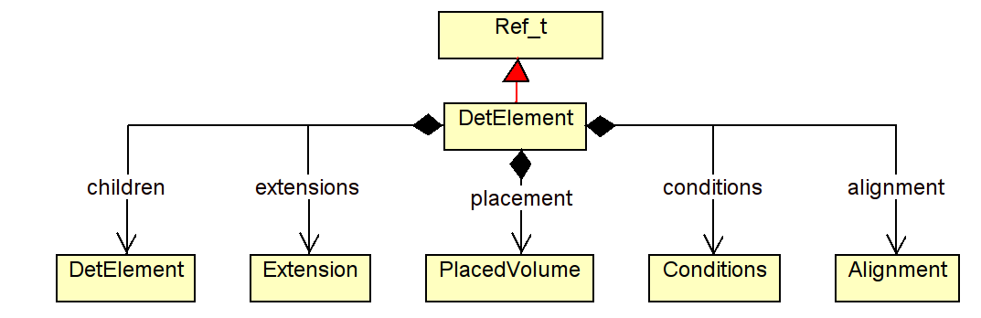
Detector elements (class DetElement) are entities which represent subdetectors or sizable parts of a subdetector. As shown in Figure 2.2, a DetElement instance has the means to provide to clients information about
-
generic properties like the detector type or the path within the DetElements hierarchy:
1    /// Access detector type (structure, tracker, calorimeter, etc.).
2    std::string type() const;
3    /// Path of the detector element (not necessarily identical to placement path!)
4    std::string path() const;
-
the detector hierarchy by exposing its children. The hierarchy may be accessed with the following API:
1    /// Add new child to the detector structure
2    DetElement& add(DetElement sub_element);
3    /// Access to the list of children
4    const Children& children() const;
5    /// Access to individual children by name
6    DetElement child(const std::string& name) const;
7    /// Access to the detector element's parent
8    DetElement parent() const;
-
its placement within the overall experiment if it represents an entire subdetector or its placement with respect to its parent if the DetElement represents a part of a subdetector. The placement path is the fully qualified path of placed volumes from the top level volume to the placed detector element.
1    /// Access to the full path to the placed object
2    std::string placementPath() const;
3    /// Access to the physical volume of this detector element
4    PlacedVolume placement() const;
5    /// Access to the logical volume of the daughter placement
6    Volume volume() const;
-
information about the environmental conditions etc. (conditions):
1    /// Access to the conditions information
2    Conditions conditions() const;
-
convenience information such as cached transformations to/from the top level volume, to/from the parent DetElement and to/from another DetElement in the hierarchy above:
1    /// Transformation from local coordinates of the placed volume to the world system
2    bool localToWorld(const Position& local, Position& global) const;
3    /// Transformation from world coordinates of the local placed volume coordinates
4    bool worldToLocal(const Position& global, Position& local) const;
5
6    /// Transformation from local coordinates of the placed volume to the parent system
7    bool localToParent(const Position& local, Position& parent) const;
8    /// Transformation from world coordinates of the local placed volume coordinates
9    bool parentToLocal(const Position& parent, Position& local) const;
10
11    /// Transformation from local coordinates of the placed volume to arbitrary parent system set as reference
12    bool localToReference(const Position& local, Position& reference) const;
13    /// Transformation from world coordinates of the local placed volume coordinates
14    bool referenceToLocal(const Position& reference, Position& local) const;
15
16    /// Set detector element for reference transformations.
17    /// Will delete existing reference transformation.
18    DetElement& setReference(DetElement reference);
-
User extension information as described in section 2.3:
1    /// Extend the detector element with an arbitrary structure accessible by the type
2    template <typename IFACE, typename CONCRETE> IFACE* addExtension(CONCRETE* c);
3    /// Access extension element by the type
4    template <class T> T* extension() const;
2.12 Sensitive Detectors
Though the concept of sensitive detectors comes from Geant4 and simulation activities, in DD4hep the sensitive detectors are the client interface to access the readout description (class Readout) with its segmentation of sensitive elements (class Segmentation) and the description of hit decoders (class IDDescriptors). As shown in Figure 2.4, these object instances are required when reconstructing data from particle collisions.
Besides the access to data necessary for reconstruction the sensitive detector also hosts Region setting (class Region and sets of cut limits (class LimitSets) used to configure the Geant4 simulation toolkit. The following code snippet shows the accessors of the SensitiveDetector class to obtain the corresponding information 2 :
1    struct SensitiveDetector: public Ref_t {
2      /// Access the hits collection name
3      const std::string& hitsCollection() const;
4      /// Access readout structure of the sensitive detector
5      Readout readout() const;
6      /// Access to the region setting of the sensitive detector (not mandatory)
7      Region region() const;
8      /// Access to the limit set of the sensitive detector (not mandatory).
9      LimitSet limits() const;
10
11      /// Extend the sensitive detector element with an arbitrary structure accessible by the type
12      template <typename IFACE, typename CONCRETE> IFACE* addExtension(CONCRETE* c);
13      /// Access extension element by the type
14      template <class T> T* extension() const;
15   };
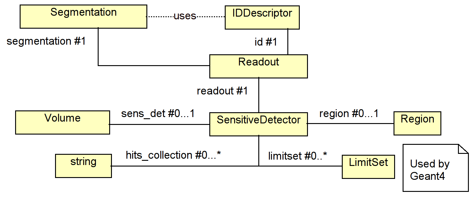
Sensitive detector objects are automatically creating using the information of the <readout> section of the XML file if a subdetector is sensitive and references a valid readout entry. In the detector constructor (or any time later) clients may add additional information to a sensitive detector object using an extension mechanism similar to the extension mechanism for detector elements mentioned earlier.
Volumes may be shared and reused in several placements. In the parallel hierarchy of detector elements as shown in Figure 1.3, the detector elements may reference unambiguously the volumes of their respective placements, but not the reverse. However, the sensitive detector setup is a single instance per subdetector. Hence it may be referenced by all sensitive Volumes of one subdetector. In the following chapters the access to the readout structure is described.
2.13 Description of the Readout Structure
2.13.2 Segmentations
2.13.3 Volume Manager
2.13.4 Static Electric and Magnetic Fields
The Readout class describes the detailed structure of a sensitive volume. The for example may be the layout of strips or pixels in a silicon detector i.e. the description of entities which would not be modeled using individual volumes and placements though this would theoretically feasible. Each sensitive element is segmented according to the Segmentation object and hits resulting from energy depositions in the sensitive volume are encoded using the IDDescriptor object.
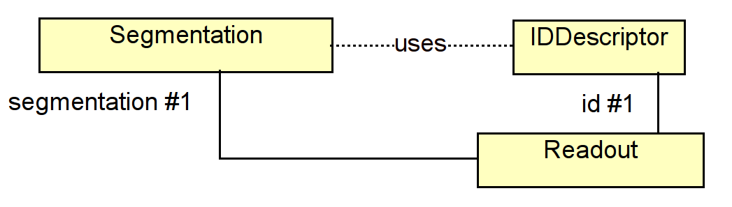
2.13.1 CellID Descriptors
IDDescriptors define the encoding of sensitive volumes to uniquely identify the location of the detector response. The encoding defines a bit-field with the length of 64 bits. The first field is mandatory called system and identifies the subdetector. All other fields define the other volumes in the hierarchy. The high bits are not necessarily mapped to small daughter volumes, but may simply identify a logical segmentation such as the strip number within a wafer of a vertex detector as shown in the following XML snippet:
1<readouts>
2  <readout name="SiVertexEndcapHits">
3    <id>system:8,barrel:3,layer:4,module:14,sensor:2,side:32:-2,strip:24</id>
4  </readout>
5<readouts>
These identifiers are the data input to segmentation classes 2.13.2, which define a user friendly API to en/decode the detector response.
2.13.2 Segmentations
Segmentations define the user API to the low level interpretation of the energy deposits in a subdetector. For technical reasons and partial religious reasons the segmentation implementation is not part of the DD4hep toolkit, but an independent package called DDSegmentation. Though the usage is an integral part of DD4hep.
2.13.3 Volume Manager
The VolumeManager is a tool to seek a look-up table of placements of sensitive volumes and their corresponding unique volume identifier, the cellID. The volume manager analyzes - once the geometry is closed - the hierarchical tree and stores the various placements in the hierarchy with respect to their identifiers. In other words the the tree is reused volumes shown e.g. in Figure 1.3 is degenerated according to the full paths of the various volumes. This use case is very common to reconstruction and analysis applications whenever a given raw-data (aka “hit”) element must be related to its geometrical location.
Figure 2.5 shows the design diagram of this component:
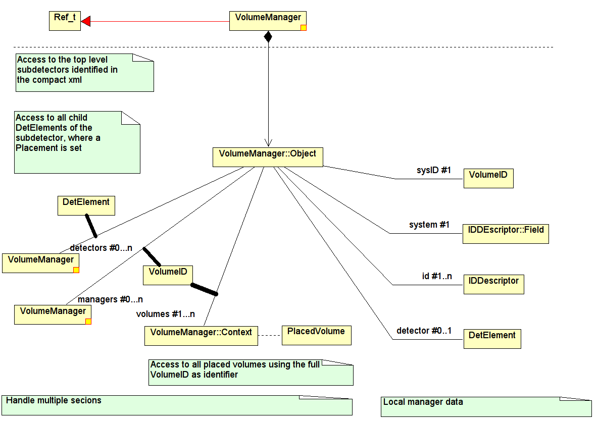
To optimize the access of complex subdetector structures, is the volume-identifier map split and the volumes of each each subdetector is stored in a separate map. This optimization however is transparent to clients. The following code extract from the header files lists the main client routines to extract volume information given a known cellID:
1  /// Lookup the context, which belongs to a registered physical volume.
2  Context* lookupContext(VolumeID volume_id) const;
3  /// Lookup a physical (placed) volume identified by its 64 bit hit ID
4  PlacedVolume lookupPlacement(VolumeID volume_id) const;
5  /// Lookup a top level subdetector detector element
6  /// according to a contained 64 bit hit ID
7  DetElement lookupDetector(VolumeID volume_id) const;
8  /// Lookup the closest subdetector detector element in the hierarchy
9  /// according to a contained 64 bit hit ID
10  DetElement lookupDetElement(VolumeID volume_id) const;
11  /// Access the transformation of a physical volume to the world coordinate system
12  const TGeoMatrix& worldTransformation(VolumeID volume_id) const;
2.13.4 Static Electric and Magnetic Fields
The generic field is described by a structure of any field type (electric or magnetic) with field components in Cartesian coordinates. The overlay field is the sum of several magnetic of electric field components and the resulting field vectors are computed by the vector addition of the individual components. The available components are described in the following. If necessary new field implementations may be added at any time: they are instantiated when necessary by the factory mechanism. Fields are described in the compact model within the <fields> tags the following example shows:
1  <fields>
2    <field name="MyMagnet" type="solenoid"  .... />
3 </fields>
The actual components are defined one by one within the <field> tags.
Constant Electric or Magnetic Fields are defined as follows:
1  <field  name="MyMagnet" type="ConstantField" field="electric">
2    <strength x="x-val" y="y-val" z="z-val"/>
3  </field>
The field attribute accepts take the values [electric,magnetic] depending on its nature.
Magnetic Dipoles are defined as follows:
1  <field name="MyMagnet" type="DipoleMagnet"
2         rmax="50*cm"
3         zmin="0*cm"
4         zmax="50*cm">
5         <dipole_coeff>1.0*tesla</dipole_coeff>
6         <dipole_coeff>0.1*tesla/pow(cm,1)</dipole_coeff>
7         <dipole_coeff>0.01*tesla/pow(cm,2)</dipole_coeff>
8  </field>
Magnetic Multipole Fields are developed according to their approximation using the multipole coefficients. The dipole is assumed to be horizontal as it is used for bending beams in large colliders i.e. the dipole field lines are vertical.
The different field components are given by:
With being “normal multipole coefficients” and the “skew multipole coefficients”. The maximal moment used is the octopole moment. The lower four moments are used to describe the magnetic field:
-
Dipole (n=1):
-
Quadrupole (n=2):
-
Sextupole (n=3):
-
Octopole (n=4):
The defined field components only apply within the shape ’volume’. If ’volume’ is an invalid shape (i.e. not defined), then the field components are valid throughout the ’universe’.
The magnetic multipoles are defined as follows:
1<field name="MyMagnet" type="MultipoleMagnet">
2  <position x="0" y="0" z="0"/>
3  <rotation x="pi" y="0" z="0"/>
4  <shape type="shape-constructor-type" .... args .... >
5<coefficient coefficient="coeff(n=1)" skew="skew(n=1)"/>
6  .... maximum of 4 coefficients ....
7  <coefficient coefficient="coeff(n=4)" skew="skew(n=4)"/>
8</field>
The shape defines the geometrical coverage of the multipole field in the origin (See section 2.9 for details). This shape may then be transformed to the required location in the detector area using the position and the rotation elements, which define this transformation.
2.14 Detector Constructors
The creation of appropriate detector constructors is the main work of a client defining his own detector. The detector constructor is a fragment of code in the form of a routine, which return a handle to the created subdetector DetElement object.
Knowing that detector constructors are the main work items of clients significant effort was put in place to ease and simplify this procedure as much as possible in order to obtain readable, still compact code hopefully easy to maintain. The interfaces to all objects, XML accessors, shapes, volumes etc. which were discussed above were optimized to support this intention.
To illustrate the anatomy of such a constructor the following code originating from an existing SiD detector concept will be analyzed. The example starts with the XML input data. Further down this section the code is shown with a detailed description of every relevant line. The object to be build is a subdetector representing a layered calorimeter, where each layer consists of a number of slices as shown in the XML snippet. These layers are then repeated a number of times.
The XML snippet describing the subdetector properties:
1  <detector id="13" name="LumiCal" reflect="true" type="CylindricalEndcapCalorimeter"
2            readout="LumiCalHits" vis="LumiCalVis" calorimeterType="LUMI">
3    <comment>Luminosity Calorimeter</comment>
4    <dimensions inner_r = "LumiCal_rmin" inner_z = "LumiCal_zmin" outer_r = "LumiCal_rmax" />
5    <layer repeat="20" >
6      <slice material = "TungstenDens24" thickness = "0.271*cm" />
7      <slice material = "Silicon" thickness = "0.032*cm" sensitive = "yes" />
8      <slice material = "Copper"  thickness = "0.005*cm" />
9      <slice material = "Kapton"  thickness = "0.030*cm" />
10      <slice material = "Air"     thickness = "0.033*cm" />
11    </layer>
12    <layer repeat="15" >
13      <slice material = "TungstenDens24" thickness = "0.543*cm" />
14      <slice material = "Silicon" thickness = "0.032*cm" sensitive = "yes" />
15      <slice material = "Copper"  thickness = "0.005*cm" />
16      <slice material = "Kapton"  thickness = "0.030*cm" />
17      <slice material = "Air"     thickness = "0.033*cm" />
18    </layer>
19  </detector>
The C++ code snippet interpreting the XML data and expanding the geometry:
1#include "DD4hep/DetFactoryHelper.h"
2#include "XML/Layering.h"
3
4using namespace std;
5using namespace dd4hep;
6
7static Ref_t create_detector(Detector& lcdd, xml_h e, SensitiveDetector sens)  {
8  xml_det_t  x_det     = e;
9  string     det_name  = x_det.nameStr();
10  bool       reflect   = x_det.reflect();
11  xml_dim_t  dim       = x_det.dimensions();
12  double     zmin      = dim.inner_z();
13  double     rmin      = dim.inner_r();
14  double     rmax      = dim.outer_r();
15  double     totWidth  = Layering(x_det).totalThickness();
16  double     z         = zmin;
17  Material   air       = lcdd.air();
18  Tube       envelope   (rmin,rmax,totWidth,0,2*M_PI);
19  Volume     envelopeVol(det_name+"_envelope",envelope,air);
20  int        layer_num = 1;
21  PlacedVolume pv;
22
23  // Set attributes of slice
24  for(xml_coll_t c(x_det,_U(layer)); c; ++c)  {
25    xml_comp_t x_layer = c;
26    double layerWidth = 0;
27    for(xml_coll_t l(x_layer,_U(slice)); l; ++l)
28      layerWidth += xml_comp_t(l).thickness();
29
30    for(int i=0, m=0, repeat=x_layer.repeat(); i<repeat; ++i, m=0)  {
31      double     zlayer = z;
32      string     layer_name = det_name + _toString(layer_num,"_layer%d");
33      Volume     layer_vol(layer_name,Tube(rmin,rmax,layerWidth),air);
34
35      for(xml_coll_t l(x_layer,_U(slice)); l; ++l, ++m)  {
36        xml_comp_t x_slice = l;
37        double     w = x_slice.thickness();
38        string     slice_name = layer_name + _toString(m+1,"slice%d");
39        Material   slice_mat  = lcdd.material(x_slice.materialStr());
40        Volume     slice_vol (slice_name,Tube(rmin,rmax,w),slice_mat);
41
42        if ( x_slice.isSensitive() )  {
43          sens.setType("calorimeter");
44          slice_vol.setSensitiveDetector(sens);
45        }
46        slice_vol.setAttributes(lcdd, x_slice.regionStr(), x_slice.limitsStr(), x_slice.visStr());
47        pv = layer_vol.placeVolume(slice_vol, Position(0,0,z-zlayer-layerWidth/2+w/2));
48        pv.addPhysVolID("slice",m+1);
49        z += w;
50      }
51      layer_vol.setVisAttributes(lcdd,x_layer.visStr());
52      Position layer_pos(0,0,zlayer-zmin-totWidth/2+layerWidth/2);
53      pv = envelopeVol.placeVolume(layer_vol,layer_pos);
54      pv.addPhysVolID("layer",layer_num);
55      ++layer_num;
56    }
57  }
58  // Set attributes of slice
59  envelopeVol.setAttributes(lcdd, x_det.regionStr(), x_det.limitsStr(), x_det.visStr());
60
61  DetElement   sdet(det_name,x_det.id());
62  Volume       motherVol = lcdd.pickMotherVolume(sdet);
63  PlacedVolume phv = motherVol.placeVolume(envelopeVol,Position(0,0,zmin+totWidth/2));
64  phv.addPhysVolID("system",sdet.id()).addPhysVolID("barrel",1);
65  sdet.setPlacement(phv);
66  if ( reflect )   {
67    phv=motherVol.placeVolume(envelopeVol, Transform3D(RotationZ(M_PI), Position(0,0,-zmin-totWidth/2)));
68    phv.addPhysVolID("system",sdet.id()).addPhysVolID("barrel",2);
69  }
70  return sdet;
71}
72
73DECLARE_DETELEMENT(CylindricalEndcapCalorimeter,create_detector);
|
| |
| 1 | The include file DetFactoryHelper.h includes all utilities to extract XML information together with the appropriate type definition. |
| 4-5 | Convenience shortcut to save us a lot of typing. |
| 7 | The entry point to the detector constructor. This routine shall be called by the plugin mechanism. |
| 8 | The functionality of the raw XML handle xml_h is rather limited. A simple assignment to a XML detector object gives us all the functionality we need. |
| 9–10 | Extracting the sub-detector name and properties from the xml handle. |
| 11–16 | Access the dimension child-element from the XML subtree, access the element’s attributes and precompute values used later. |
| 17 | Retrieve a reference to the “air” material from Detector. |
| 18–19 | Construct the envelope volume shaped as a tube made out of air. |
| 24 | Now the detector can be built: We loop over all layers types and over each layer type as often as necessary (attribute: repeat).The XML collection object will return all child elements of x_detwith a tag-name “layer”. Note the macro _U(layer): When using Xerces-C as an XML parser, it will expand to the reference to an object containing the unicode value of the string “layer”. The full list of predefined tag names can be found in the include file XML/UnicodeValues.h.If a user tag is not part in the precompiled tag list, the corresponding Unicodestring may be created with the macro _Unicode(layer) or Unicode("layer"). |
| 25 | Convenience assignment to extract attributes of the layer element. |
| 26–28 | Compute total layer width. |
| 30 | Create repeat number of layers of the same type. |
| 31-33 | Create the named envelope volume with a tube shape containing all slices of this layer. |
| 35-50 | Create the different layer-slices with a tube shape and the corresponding material as indicated in the XML data. |
| 42-45 | If the slice is sensitive i.e. is instrumented and supposed to deliver signals from particle passing, the sensitive detector component of this detector needs to be attached to the slice. |
| 46 | Set visualization and Geant4 attributes to the slice volume. If the attributes are not present, they will be ignored. |
| 47 | Now the created slice volume will be placed inside the mother, the layer envelope at the correct position. This operation results in the creation of a PlacedVolume. |
| 48 | It identify uniquely every slice within the layer an identifier (here the number of the created slice) is attached. This identifier must be present in the bitmap defined by the IDDescriptor of this subdetector. |
| 52-55 | Same as 46-48, but now the created layer volume is placed in the envelope of the entire subdetector. |
| 59 | Set envelope attributes. |
| 61 | Construct the main detector element of this subdetector.This will be the unique entry point to access any information of the subdetector. Note: the subdetector my consist of a hierarchy of detector elements.For example each layer could be described by its own DetElement and all layer-DetElement instances being children of the subdetector instance. |
| 62-62 | Place the subdetector envelope into its mother (typically the top level (world) volume). |
| 64-65 | Add the missing IDDescriptor identifiers to complete the bitmap. |
| 66 | Store the placement in the subdetector detector element in order to make it available to later clients of this DetElement. |
| 67-69 | Endcap calorimeters typically are symmetric i.e. an endcap is located on each side of the barrel. To easy such reflections the entire endcap structure can be copied and placed again. |
| 70 | All done. Return the created subdetector element to the caller for registration. |
| 73 | Very important: Without the registration of the construction function to the framework, the corresponding plugin will not be found. The macro has two arguments: firstly the plugin name which is identical to the detector type in the XML snippet and secondly the function to be called at construction time. |
2.15 Tools and Utilities
2.15.2 Geometry Conversion
2.15.3 Overlap checking
2.15.4 Geometry checking
2.15.5 Directional Material Scans
2.15.6 Plugin Test Program
2.15.1 Geometry Visualization
Visualizing the geometry is an important tool to debug and validate the constructed detector. Since DD4hep uses the ROOT geometry package, all visualization tools from ROOT are automatically supported. This is in the first place the OpenGL canvas of ROOT and all elaborated derivatives thereof such as event displays etc. Figure 2.6 shows as an example the subdetector example from the SiD detector design discussed in section 2.14.
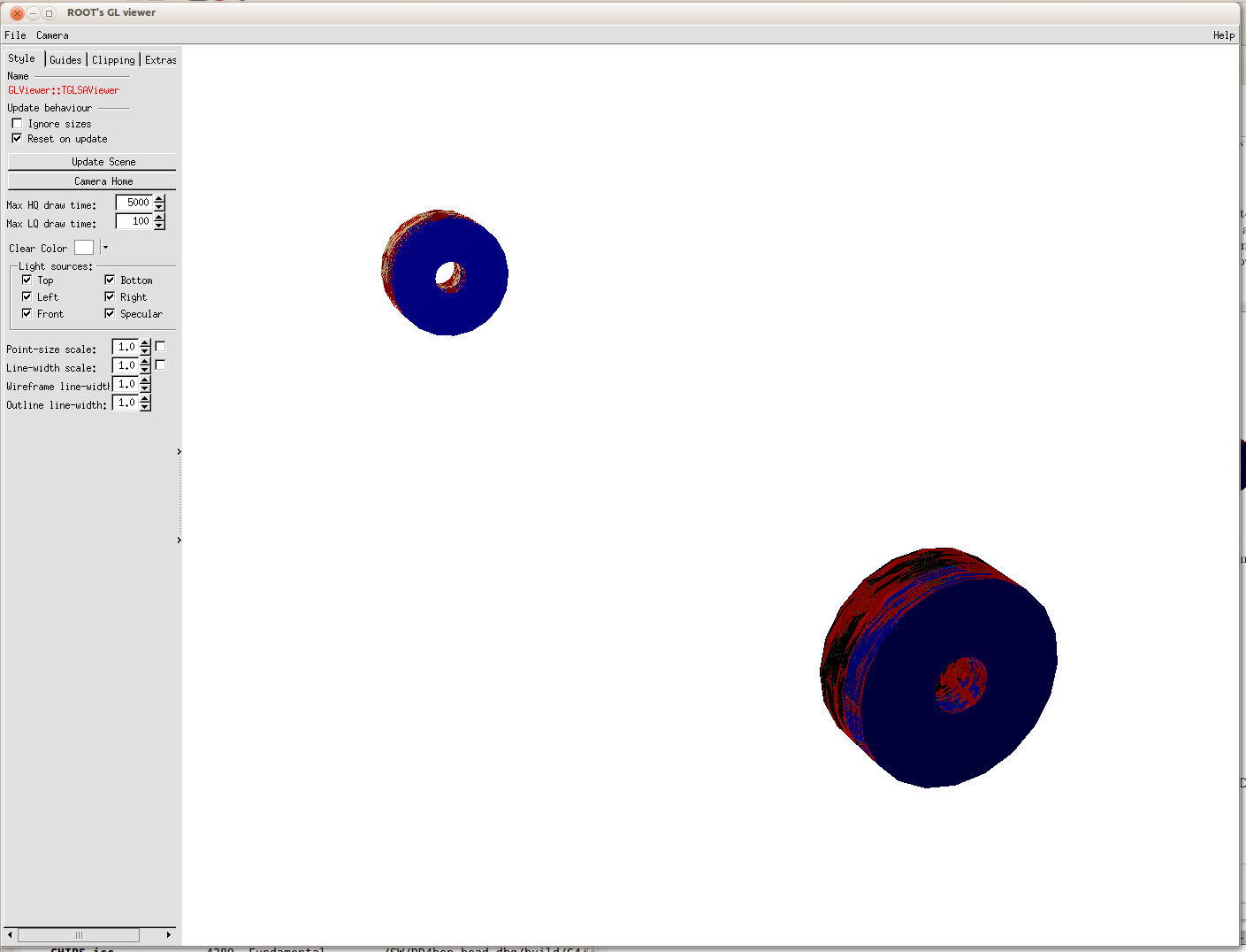
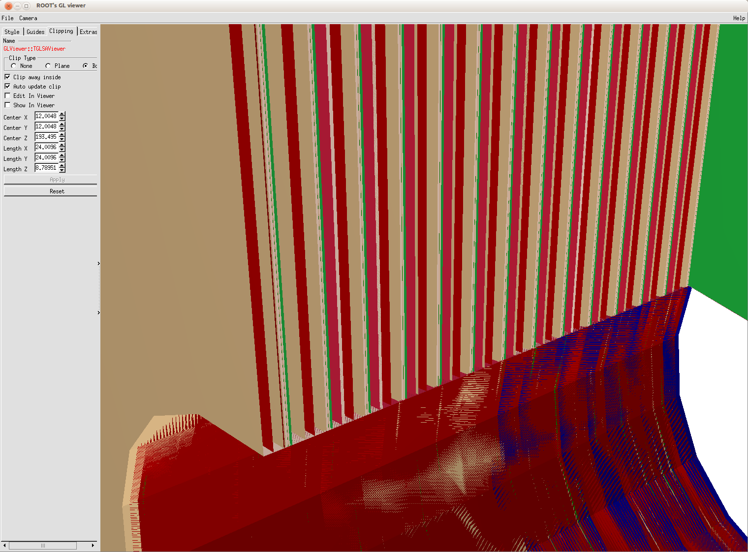
The command to create the display is part of the DD4hep release:
1$> geoDisplay -arg [arg-value] <path to the \texttt{XML} file containing the detector description>
2With -arg being (optionally):
3       -compact       <file>       Specify the compact geometry file
4                    [REQUIRED]     At least one compact geo file is required!
5       -detector      <string>     Top level DetElement path. Default: '/world'
6                    [OPTIONAL]
7       -option        <string>     ROOT Draw option.    Default: 'ogl'
8                    [OPTIONAL]
9       -level         <number>     Visualization level  [TGeoManager::SetVisLevel]  Default: 4
10                    [OPTIONAL]
11       -visopt        <number>     Visualization option [TGeoManager::SetVisOption] Default: 1
12                    [OPTIONAL]
13       -load                       Only load the geometry. Do not invoke the display
14                    [OPTIONAL]
15       -help                       Print this help output
16                    [OPTIONAL]
2.15.2 Geometry Conversion
ROOT TGeo is only one representation of a detector geometry. Other applications may require other representation. In particular two other are worth mentioning:
-
Detector [9] the geometry representation used to simulate the ILC detector design with the slic application.
-
GDML [10] a geometry markup language understood by Geant4 and ROOT.
Both conversions are supported in DD4hep with the geoConverter application:
1  geoConverter -opt [-opt]
2        Action flags:               Usage is exclusive, 1 required!
3        -compact2description        Convert compact xml geometry to description.
4        -compact2gdml               Convert compact xml geometry to gdml.
5        -compact2pandora            Convert compact xml to pandora xml.
6        -compact2tgeo               Convert compact xml to TGeo in ROOT file.
7        -compact2vis                Convert compact xml to visualisation attrs
8
9        -input  <file>  [REQUIRED]  Specify input file.
10        -output <file>  [OPTIONAL]  Specify output file.
11                                    if no output file is specified, the output
12                                    device is stdout.
13        -ascii          [OPTIONAL]  Dump visualisation attrs in csv format.
14                                    [Only valid for -compact2vis]
15        -destroy        [OPTIONAL]  Force destruction of the Detector instance
16                                    before exiting the application
17        -volmgr         [OPTIONAL]  Load and populate phys.volume manager to
18                                    check the volume ids for duplicates etc.
2.15.3 Overlap checking
Overlap checks are an important tool to verify the consistency of the implemented geometrical design. As in the real world, where overlaps are impossible, also simulated geometries may not have overlaps. In simulation overlaps tend to create particle reflections possibly leading to infinite loops.
1    Usage: checkOverlaps.py [options]
2    python <install>/bin/checkOverlaps.py --help
3
4    Check TGeo geometries for overlaps.
5
6    Options:
7      -h, --help                        show this help message and exit
8      -c <FILE>, --compact=<FILE>       Define LCCDD style compact xml input
9      -p <boolean>, --print=<boolean>   Print overlap information to standard output
10                                        (default:True)
11      -q, --quiet                       Do not print (disable --print)
12      -t <double number>, --tolerance=<double number>
13                                        Overlap checking tolerance. Unit is in [mm].
14                                        (default:0.1 mm)
15      -o <string>, --option=<string>    Overlap checking option ('' or 's')
2.15.4 Geometry checking
Perform extensive geometry checks. For details and up to date information please refer to the ROOT documentation of the class TGeoManager:
-
Member function TGeoManager::CheckGeometry and
-
Member function TGeoManager::CheckGeometryFull
1    python <install>DD4hep/bin/checkGeometry.py --help
2    Usage: checkGeometry.py [options]
3
4    TGeo Geometry checking.
5
6    Options:
7      -h, --help                            show this help message and exit
8      -c <FILE>, --compact=<FILE>           Define LCCDD style compact xml input
9      -f <boolean>, --full=<boolean>        Full geometry checking
10      -n <integer>, --ntracks=<integer>     Number of tracks [requires 'full']
11      -x <double>, --vx=<double>            X-position of track origin vertex [requires 'full']
12      -y <double>, --vy=<double>            Y-position of track origin vertex [requires 'full']
13      -z <double>, --vz=<double>            Z-position of track origin vertex [requires 'full']
14      -o <string>, --option=<string>        Geometry checking option default:ob
The full geometry check performs the TGeoManager:CheckGeometryFull following actions:
-
if option contains ’o’: Optional overlap checkings (by sampling and by mesh).
-
if option contains ’b’: Optional boundary crossing check + timing per volume.
- STAGE 1
-
extensive overlap checking by sampling per volume. Stdout need to be checked by user to get report, then TGeoVolume::CheckOverlaps(0.01, "s") can be called for the suspicious volumes.
- STAGE 2
-
normal overlap checking using the shapes mesh - fills the list of overlaps.
- STAGE 3:
-
shooting NTRACKS rays from vertex (vx,vy,vz) and counting the total number of crossings per volume (rays propagated from boundary to boundary until geometry exit). Timing computed and results stored in a histogram.
- STAGE 4:
-
shooting 1 mil. random rays inside EACH volume and calling FindNextBoundary() + Safety() for each call. The timing is normalized by the number of crossings computed at stage 2 and presented as percentage. One can get a picture on which are the most “burned” volumes during transportation from geometry point of view. Another plot of the timing per volume vs. number of daughters is produced.
2.15.5 Directional Material Scans
Print the materials on a straight line between the two given points:
1materialScan
2 usage: print_materials compact.xml x0 y0 z0 x1 y1 z1
3        -> prints the materials on a straight line between the two given points ( unit is cm)
materialScan uses the python bindings provided by Geant4 and may be not always available. Alternatively the command print_materials may be used, which does not use the python binding, but produces less pretty output.
2.15.6 Plugin Test Program
The plugin tester loads a given geometry and the executes a plugin defined at the command line. The main purpose of this program is to quickly invoke new detector plugins while developing. The arguments for this program are:
1    geoPluginRun -opt [-opt]
2
3        -plugin <name>  [REQUIRED]  Plugin to be executed and applied.
4        -input  <file>  [OPTIONAL]  Specify geometry input file.
5        -build_type <number/string> Specify the build type
6                     [OPTIONAL]     MUST come immediately after the -compact input.
7                                    Default for each file is: BUILD_DEFAULT [=1]
8                                    Allowed values: BUILD_SIMU [=1], BUILD_RECO [=2] or BUILD_DISPLAY [=3]
9        -destroy     [OPTIONAL]     Force destruction of the LCDD instance
10                                    before exiting the application
11        -volmgr      [OPTIONAL]     Load and populate phys.volume manager to
12                                    check the volume ids for duplicates etc.
13        -print      <number/string> Specify output level. Default: INFO(=3)
14                     [OPTIONAL]     Allowed values: VERBOSE(=1), DEBUG(=2),
15                                    INFO(=3), WARNING(=4), ERROR(=5), FATAL(=6)
16                                    The lower the level, the more printout...
To invoke plugins using this utility is very simple and any number of plugins may be chained to produce the required result. This is very convenient e.g. to run tests:
1  $> geoPluginRun -input <compact geometry file> \
2                  -plugin <plugin-name-1> <plugin-arg-1>  <plugin-arg-2> ....
3                  -plugin <plugin-name-2> <plugin-arg-1>  <plugin-arg-2> ....
4                  -plugin <plugin-name-3> <plugin-arg-1>  <plugin-arg-2> ....
5                  ....
2.16 Standard Plugins
2.16.2 Execute a Function in a Library
2.16.3 Start the ROOT Interpreter
2.16.4 Start the DD4hep UI
2.16.5 Dump GDML Tables of the TGeoManager
2.16.6 Dump Optical Surfaces of the TGeoManager
2.16.7 Dump Skin Surfaces of the TGeoManager
2.16.8 Dump Border Surfaces of the TGeoManager
2.16.9 Dump the Element/Material Table of the TGeoManager
2.16.10 Load and Interprete XML file
2.16.11 Load and Interprete XML Element
2.16.12 Load and Initialize the DD4hep Volume Manager
2.16.13 Dump Detector Description to ROOT file
2.16.14 Load Detector Description from ROOT file
2.16.15 Dump Geometry to ROOT file
2.16.16 Dump DetElement/Volume Tree
2.16.17 Fill DetElement Cache
These plugins are partially used by DD4hep itself and are invoked from therein, but can as well be initiated from the above mentioned plugin test program.
2.16.1 Geometry Display
This plugin may be used to invoke the geometry display and start the ROOT interpreter:
1    Usage: -plugin DD4hep_GeometryDisplay  -arg [-arg]
2           Invoke the ROOT geometry display using the factory mechanism.
3             -detector <string> Top level DetElement path. Default: '/world'
4             -option   <string> ROOT Draw option.    Default: 'ogl'
5             -level    <number> Visualization level  [TGeoManager::SetVisLevel]  Default: 4
6             -visopt   <number> Visualization option [TGeoManager::SetVisOption] Default: 1
7             -load              Only load the geometry. Do not invoke the display
8             -help              Print this help output
9
10    For details see also: DDCore/src/plugins/StandardPlugins.cpp
2.16.2 Execute a Function in a Library
Plugin to invoke a C function in a library. The plugin automatically loads the library and executes the function. The function may not require arguments. The function is identified by it’s linker name. Hence, to not need to deal with linker name mangling export such functions with extern “C”.
1    Usage: -plugin DD4hep_Function -arg [-arg]
2             Execute a function without arguments inside a library.
3           -library   <string>    Library to be loaded
4           -function  <string>    name of the entry point to be executed.
5
6    For details see also: DDCore/src/plugins/StandardPlugins.cpp
2.16.3 Start the ROOT Interpreter
To trigger the start of the ROOT interpreter, invoke the plugin. Additional arguments are assumed to be command, which should be evaluated.
1    Usage: -plugin DD4hep_Rint -arg [-arg]
2             Start the ROOT interpreter. Optionally process one or several commands.
3
4    For details see also: DDCore/src/plugins/StandardPlugins.cpp
2.16.4 Start the DD4hep UI
The DD4hep UI is a mediator to interactively interact more easily with the DD4hep instance from the ROOT command prompt. See the definition file DDCore/include/DD4hep/DD4hepUI.h for details. An instance of the DD4hepUI class is generated and made available to ROOT by the global pointer gDD4hepUI. Any argument is ignored.
1    Usage: -plugin DD4hep_InteractiveUI
2
3    For details see also: DDCore/src/plugins/StandardPlugins.cpp
2.16.5 Dump GDML Tables of the TGeoManager
The plugin simply dumps the GDML tables associated to the TGeoManager instance to stdout. Useful to verify the parsed content. Any argument is ignored.
1    Usage: -plugin DD4hep_Dump_GDMLTables
2
3    For details see also: DDCore/src/plugins/StandardPlugins.cpp
2.16.6 Dump Optical Surfaces of the TGeoManager
The plugin simply dumps the optical surfaces associated to the TGeoManager instance to stdout. Useful to verify the parsed content. Any argument is ignored.
1    Usage: -plugin DD4hep_Dump_OpticalSurfaces
2
3    For details see also: DDCore/src/plugins/StandardPlugins.cpp
2.16.7 Dump Skin Surfaces of the TGeoManager
The plugin simply dumps the skin surfaces associated to the TGeoManager instance to stdout. Useful to verify the parsed content. Any argument is ignored.
1    Usage: -plugin DD4hep_Dump_SkinSurfaces
2
3    For details see also: DDCore/src/plugins/StandardPlugins.cpp
2.16.8 Dump Border Surfaces of the TGeoManager
The plugin simply dumps the border surfaces associated to the TGeoManager instance to stdout. Useful to verify the parsed content. Any argument is ignored.
1    Usage: -plugin DD4hep_Dump_BorderSurfaces
2
3    For details see also: DDCore/src/plugins/StandardPlugins.cpp
2.16.9 Dump the Element/Material Table of the TGeoManager
The plugin dumps all elements stored in the TGeoManager instance to stdout or to file. Optionally the output can be generated in XML understood by DD4hep in order to e.g. export the elements used in the apparatus. Useful to verify the parsed content.
1    Usage:  -plugin DD4hep_ElementTable -opt [-opt]
2                  -type   <string>    Output format: text or xml
3                  -output <file-name> Output file specifier (xml only)
4
5    For details see also: DDCore/src/plugins/StandardPlugins.cpp
To dump the material table, use the plugin DD4hep_MaterialTable.
2.16.10 Load and Interprete XML file
Load and interprete an XML file with DD4hep. The root tag name of the file defines the factory name to be called to analyse the content. The optional build type is a flag passed to the Detector entity and may be used for more detailed interpretation.
1    Usage:  -plugin DD4hep_XMLLoader <file-uri> <build-type>
2
3    For details see also: DDCore/src/plugins/StandardPlugins.cpp
2.16.11 Load and Interprete XML Element
Interprete a single XML element. The root tag name of the file defines the factory name to be called to analyse the content. The optional build type is a flag passed to the Detector entity and may be used for more detailed interpretation. This plugin can only be used, since the argument to a pointer to an XML::Handle is passed.
1    Usage:  -plugin DD4hep_XMLProcessor <pointer-to-xml-element> <build-type>
2
3    For details see also: DDCore/src/plugins/StandardPlugins.cpp
2.16.12 Load and Initialize the DD4hep Volume Manager
To load and initialize the DD4hep volume manager object, use:
1    Usage:  -plugin DD4hep_VolumeManager
2
3    For details see also: DDCore/src/plugins/StandardPlugins.cpp
Any argument is ignored. Please note: the detector description must be full initialized before this plugin may be called. Anything else results in incomplete content.
2.16.13 Dump Detector Description to ROOT file
This plugin saves the full detector description object to a ROOT file including geometry and structural setup. Please note, that for reading DD4hep is required to resolve the necessary dictionaries. However, this method may serve to produce well defined snapshots e.g. for mass production.
1     Usage: -plugin DD4hep_Geometry2ROOT -arg [-arg]
2             -output <string>         Output file name.
3
4    For details see also: DDCore/src/plugins/StandardPlugins.cpp
2.16.14 Load Detector Description from ROOT file
Once saved, load the DD4hep detector description into memory.
1     Usage: -plugin DD4hep_RootLoader -arg [-arg]
2             -input <string>         Input file name.
3
4    For details see also: DDCore/src/plugins/StandardPlugins.cpp
2.16.15 Dump Geometry to ROOT file
The plugin saves the geometry part of the detector description to ROOT. Only ROOT is required to read this information.
1    Usage: -plugin DD4hep_Geometry2TGeo -arg [-arg]
2             -output <string>         Output file name.
3
4    For details see also: DDCore/src/plugins/StandardPlugins.cpp
2.16.16 Dump DetElement/Volume Tree
Dump for verification and debugging the DetElement or Volume tree of the detector description. Both plugin are very similar, once with emphasis on the ejected DetElement information, once with emphasis on the geometry information.
1   Usage -plugin DD4hep_DetectorDump / DD4hep_DetectorVolumeDump -arg [-arg]
2
3         --sensitive             Process only sensitive volumes.
4          -sensitive             dto.
5         --no-sensitive          Invert sensitive only flag.
6          -no-sensitive          dto.
7         --shapes                Print shape information.
8          -shapes                dto.
9         --positions             Print position information.
10          -positions             dto.
11         --materials             Print material information.
12          -materials             dto.
13         --detector    <path>    Process elements only if <path> is part of the DetElement path.
14          -detector    <path>    dto.
15          -level       <number>  Maximal depth to be explored by the scan
16         --level       <number>  dto.
17          -volids                Print volume identifiers of placements.
18         --volids                dto.
19
20    For details see also: DDCore/src/plugins/StandardPlugins.cpp
2.16.17 Fill DetElement Cache
The DetElement instances may cache on demand the transformations of their ideal placements to the world coordinate system. To fill this cache immediately rather than on demand use this plugin. Depending on the top element passed, this caching mechanism can also be applied to some sub-detectors.
1    Usage: -plugin DD4hep_DetElementCache  -arg [-arg]
2             -detector <string>  Top level DetElement path. Default: '/world'
3       --detector <string> dto.
4
5    For details see also: DDCore/src/plugins/StandardPlugins.cpp
2.17 Shape and Volume Plugins
2.17.2 Scaled Shape Construction
2.17.3 Box Shape Construction
2.17.4 Half-Space Construction
2.17.5 Cone Construction
2.17.6 Polycone Construction
2.17.7 Cone Segment Construction
2.17.8 Tube Construction
2.17.9 Trap Construction
2.17.10 Regular Trapezoid (TRD1) Construction
2.17.11 Irregular Trapezoid (TRD2) Construction
2.17.12 Torus Shape Construction
2.17.13 Sphere Shape Construction
2.17.14 Paraboloid Shape Construction
2.17.15 Hyperboloid Shape Construction
2.17.16 Regular Polyhedron Construction
2.17.17 Irregular Polyhedron Construction
2.17.18 Eight-Point Solid Construction
2.17.19 Tessellated Solid Construction
2.17.20 Boolean Shape Construction
Shape plugins can be used to create shapes and volumes using uniquely xml constructs without the need of extra code. Often useful when describing passive objects of an apparatus. DD4hep supports all commonly used and supported shapes by TGeo, and allows the abstract creation of these shapes using the plugin mechanism. We list here the shapes, which are supported by the plugin mechanism. The creation of shapes can be triggered using any XML element matching a given pattern. The constructor is accessible as follows:
1#include <XML/Utilities.h>
2
3  Detector& det = ...;
4  xml::Element element = ...;
5  std::string shape_type = "Box";
6  Solid solid = dd4hep::xml::createShape(description, shape_type, element);
where the XML Element element must supply all required information to actually create the shape of a given type. To create shapes with the factory mechanism, the shape constructors as present in DDCore/include/DD4hep/Shapes.h must be met.
2.17.1 Assembly Shape Construction
The xml entity ’element’ must look like the following:
1   <some-tag name="my-assembly"  ......further xml-attributes not looked at .... >
2        ... further optional xml-elements not looked at ....
3   </some-tag>
The name attribute is optional. If present the created TGeoShapeAssembly will be given the supplied identifier.
2.17.2 Scaled Shape Construction
The xml entity ’element’ must look like the following:
1   <some-tag name="my-solid" x="1.0" y="2.0" z="3.0" ... further xml-attributes not looked at .... >
2        <shape>  ......  </shape>
3        ... further optional xml-elements not looked at ....
4   </some-tag>
The name attribute is optional. If present the created Solid will be given the supplied identifier.
-
, , are the values of scaling.
-
<shape>: some shape descriptor understood by a DD4hep factory.
2.17.3 Box Shape Construction
The xml entity ’element’ must look like the following:
1    <some-tag name="my-box" x="1.0*cm" y="2.0*cm" z="3.0*cm" ... further xml-attributes not looked at .... >
2         ... further optional xml-elements not looked at ....
3    </some-tag>
The name attribute is optional. If present the created Solid will be given the supplied identifier. , , denote the half-side lengths of the created solid.
2.17.4 Half-Space Construction
The xml entity ’element’ must look like the following:
1   <some-tag name="my-box" ... further xml-attributes not looked at .... >
2      <point  x="1.0*cm" y="2.0*cm" z="3.0*cm"/>
3      <normal x="1.0" y="0.0" z="0.0"/>
4        ... further optional xml-elements not looked at ....
5   </some-tag>
and are the defining entities for the solid.
2.17.5 Cone Construction
The xml entity ’element’ must either look like the following:
1   <some-tag  name="my-cone" z="10*cm" rmin1="1*cm" rmax1="2.cm" rmin2="2*cm" rmax2="4*cm"
2              ... further xml-attributes not looked at .... >
3         ... further optional xml-elements not looked at ....
4   </some-tag>
is optional, , have default values if not explicitly set.
2.17.6 Polycone Construction
The xml entity ’element’ must look like the following:
1   <some-tag name="my-polycone" startphi="0*rad" deltaphi="2*pi" ... further xml-attributes not looked at .... >
2      <zplane rmin="1.0*cm" rmax="2.0*cm"/>
3      <zplane rmin="2.0*cm" rmax="4.0*cm"/>
4      <zplane rmin="3.0*cm" rmax="6.0*cm"/>
5      <zplane rmin="4.0*cm" rmax="8.0*cm"/>
6      <zplane rmin="5.0*cm" rmax="10.0*cm"/>
7        ... further optional xml-elements not looked at ....
8   </some-tag>
is optional, , have default values if not explicitly set.
2.17.7 Cone Segment Construction
This shape implements for historical reasons two alternative constructors, which are automatically recognized depending on the supplied attributes. The xml entity ’element’ must either look like the following:
1   <some-tag name="my-polycone" rmin1="1*cm" rmax1="2.cm"  rmin1="2*cm" rmax1="3.cm"
2                                startphi="0*rad" deltaphi="pi" ... further xml-attributes not looked at .... >
3        ... further optional xml-elements not looked at ....
4   </some-tag>
is optional, , have default values if not explicitly set. Otherwise the following pattern must be fulfilled (DEPRECATED):
1   <some-tag name="my-polycone" rmin1="1*cm" rmax1="2.cm"  rmin1="2*cm" rmax1="3.cm"
2                                phi1="0*rad" phi2="pi" ... further xml-attributes not looked at .... >
3        ... further optional xml-elements not looked at ....
4   </some-tag>
is optional, , use default values if not explicitly set.
2.17.8 Tube Construction
This shape implements for historical reasons two alternative constructors, which are automatically recognized depending on the supplied attributes. The xml entity ’element’ must either look like the following:
1   <some-tag name="my-tube" rmin="1*cm" rmax="2.cm"
2                             startphi="0*rad" deltaphi="pi" ... further xml-attributes not looked at .... >
3        ... further optional xml-elements not looked at ....
4   </some-tag>
is optional, , have default values if not explicitly set. Otherwise the following pattern must be fulfilled (DEPRECATED):
1    <some-tag name="my-tube" rmin="1*cm" rmax="2.cm"
2                             phi1="0*rad" phi2="pi" ... further xml-attributes not looked at .... >
is optional, , use default values if not explicitly set.
2.17.9 Trap Construction
This shape implements two alternative constructors, which are automatically recognized depending on the supplied attributes. The xml entity ’element’ must either look like the following:
1   <some-tag name="my-tube" z="2*cm" theta="0" phi="0"
2                            y1="1*cm" x1="1*cm" x2="2.cm" alpha1="0"
3                            y2="2.cm" x3="2*cm" x4="2*cm" alpha2="pi"
4                             ... further xml-attributes not looked at .... >
5   </some-tag>
The alternative constructor takes the following arguments:
1   <some-tag  dx="1*cm" dy="2.cm" dz="2*cm" pLTX="..." ... further xml-attributes not looked at .... >
2         ... further optional xml-elements not looked at ....
3   </some-tag>
is optional, , have default values if not explicitly set. This constructor is a reduces form for a subset of trap shapes. The relationship between the two constructors is as follows:
1  z      = 0.5*dz;
2  theta  = 0;
3  phi    = 0;
4  x1     = 0.5 * dx;
5  y1     = 0.5 * dy;
6  x2     = 0.5 * pLTX;
7  alpha1 = atan(0.5*(pLTX - dx)/dy);
8  x3     = 0.5 * dx;
9  y2     = 0.5 * dy;
10  x4     = 0.5 * pLTX;
11  alpha2 = alpha1;
2.17.10 Regular Trapezoid (TRD1) Construction
The xml entity ’element’ must look like the following:
1    <some-tag name="my-trd1" x1="1*cm" x2="2*cm" y="1*cm" z="2*cm"
2         ... further xml-attributes not looked at .... >
3         ... further optional xml-elements not looked at ....
4    </some-tag>
The name attribute is optional. If present the created Solid will be given the supplied identifier.
2.17.11 Irregular Trapezoid (TRD2) Construction
The xml entity ’element’ must look like the following:
1    <some-tag name="my-trd2" x1="1*cm" x2="2*cm" y1="1*cm" y2="2*cm" z="2*cm"
2         ... further xml-attributes not looked at .... >
3         ... further optional xml-elements not looked at ....
4    </some-tag>
The name attribute is optional. If present the created Solid will be given the supplied identifier.
2.17.12 Torus Shape Construction
This shape implements for historical reasons two alternative constructors, which are automatically recognized depending on the supplied attributes. The xml entity ’element’ must look like the following:
1    <some-tag name="my-torus" r="10*cm" rmin="1*cm" rmax="2.cm"
2                              startphi="0*rad" deltaphi="2*pi" ... further xml-attributes not looked at .... >
3         ... further optional xml-elements not looked at ....
4    </some-tag>
The name attribute is optional. If present the created Solid will be given the supplied identifier. , and have default values and are optional.
The alternative constructor takes the following arguments:
1   <some-tag name="my-tube" r="10*cm" rmin="1*cm" rmax="2.cm"
2                            phi1="0*rad" phi2="2*pi" ... further xml-attributes not looked at .... >
3        ... further optional xml-elements not looked at ....
4   </some-tag>
The name attribute is optional. If present the created Solid will be given the supplied identifier. , and have default values and are optional.
2.17.13 Sphere Shape Construction
The xml entity ’element’ must look like the following:
1    <some-tag name="my-sphere" rmin="1*cm" rmax="10*cm" starttheta="0" deltatheta="pi" startphi="0" deltaphi="2*pi"
2                              ... further xml-attributes not looked at .... >
3         ... further optional xml-elements not looked at ....
4    </some-tag>
The name attribute is optional. If present the created Solid will be given the supplied identifier. , and , and have default values and are optional.
2.17.14 Paraboloid Shape Construction
The xml entity ’element’ must look like the following:
1    <some-tag name="my-paraboloid" rmin="1*cm" rmax="2*cm" dz="1*cm" ... further xml-attributes not looked at .... >
2        ... further optional xml-elements not looked at ....
3    </some-tag>
The name attribute is optional. If present the created Solid will be given the supplied identifier. has a default value and is optional.
2.17.15 Hyperboloid Shape Construction
The xml entity ’element’ must look like the following:
1    <some-tag name="my-hyperboloid" rmin="1*cm" inner_stereo="50*degree" rmax="2*cm"
2                                    rmax="2*cm" outer_stereo="pi/2"
3                                    dz="5*cm"   ... further xml-attributes not looked at .... >
4        ... further optional xml-elements not looked at ....
5    </some-tag>
The name attribute is optional. If present the created Solid will be given the supplied identifier.
2.17.16 Regular Polyhedron Construction
The xml entity ’element’ must look like the following:
1    <some-tag name="my-polyhedron"  numsides="5" rmin="1*cm" rmax="2*cm" dz="5*cm"
2                                    dz="5*cm" ... further xml-attributes not looked at .... >
3        ... further optional xml-elements not looked at ....
4    </some-tag>
The name attribute is optional. If present the created Solid will be given the supplied identifier.
2.17.17 Irregular Polyhedron Construction
The xml entity ’element’ must look like the following:
1    <some-tag name="my-polyhedron" numsides="5" startphi="0" deltaphi="2*pi" ... further xml-attributes not looked at .... >
2      <plane rmin="1*cm" rmax="2*cm" z="1*cm"/>
3      <plane rmin="2*cm" rmax="3*cm" z="2*cm"/>
4      <plane rmin="2*cm" rmax="4*cm" z="4*cm"/>
5         ... further optional xml-elements not looked at ....
6    </some-tag>
7    ... further optional xml-elements not looked at ....
8    </some-tag>
The name attribute is optional. If present the created Solid will be given the supplied identifier. A minimum of 2 z-planes is required.
2.17.18 Eight-Point Solid Construction
To be written.
2.17.19 Tessellated Solid Construction
To be written.
2.17.20 Boolean Shape Construction
To be written.
2.18 Readout Segmentation
Segmentation plugins are used to impose an artificial super-structure onto sensitive elements such as a grid for pixel detectors etc. DD4hep supports several such segmentations, which are internally created with the plugin mechanism, which also allows to easily extend the existing palette of segmentations.