1 Introduction and General Overview
The development of a coherent set of software tools for the description of High Energy Physics detectors from a single source of information has been on the agenda of many experiments for decades. Providing appropriate and consistent detector views to simulation, reconstruction and analysis applications from a single information source is crucial for the success of the experiments. Detector description in general includes not only the geometry and the materials used in the apparatus, but all parameters describing e.g. the detection techniques, constants required by alignment and calibration, description of the readout structures, conditions data, etc.
The design of the DD4hep toolkit [1] is shaped on the experience of detector description systems, which were implemented for the LHC experiments, in particular the LHCb experiment [2, 3], as well as the lessons learnt from other implementations of geometry description tools developed for the Linear Collider community [4, 5]. Designing a coherent set of tools, with most of the basic components already existing in one form or another, is an opportunity for getting the best of all existing solutions. DD4hep aims to widely reuse used existing software components, in particular the ROOT geometry package [6], part of the ROOT project [7], a tool for building, browsing, navigating and visualizing detector geometries. The code is designed to optimize particle transport through complex structures and works standalone with respect to any Monte-Carlo simulation engine. The ROOT geometry package provides sophisticated 3D visualization functionality, which is ideal for building detector and event displays. The second component is the Geant4 simulation toolkit [8], which is used to simulate the detector response from particle collisions in complex designs. In DD4hep the geometrical representation provided by ROOT is the main source of information. In addition DD4hep provides the automatic conversions to other geometrical representations, such as Geant4, and the convenient usage of these components without the reinvention of the existing functionality.
In Section 1.1 the scope and the high-level requirements of the DD4hep toolkit are elaborated (in the following also called “the toolkit”). This is basically the high-level vision of the provided functionality to the experimental communities. In Section 1.2 the high-level or architectural design of the toolkit is presented, and in subsequent subsections design aspects of the various functional components and their interfaces will be introduced.
1.2 Toolkit Design
1.2.1 The Compact Detector Description
1.2.2 Detector Constructors
1.3 Generic Detector Description Model
1.3.1 Detector Element Tree versus the Geometry Hierarchy
1.3.2 Extensions and Views
1.4 Simulation Support
1.5 Detector Alignment Support
1.1 Project Scope and Requirements
The detector description should fully describe and qualify the detection apparatus and must expose access to all information required to interpret event data recorded from particle collisions. Experience from the LHC experiments has shown that a generalized view, not limited only to geometry, is very beneficial in order to obtain a coherent set of tools for the interpretation of collision data. This is particularly important in later stages of the experiment’s life cycle, when a valid set of detector data must be used to analyze real or simulated detector response from particle collisions. An example would be an alignment application, where time dependent precise detector positions are matched with the detector geometry.
The following main requirements influenced the design of the toolkit:
- Full Detector Description:
-
the toolkit should be able to manage the data describing the detector geometry, the materials used when building the structures, visualization attributes, detector readout information, alignment, calibration and environmental parameters - all that is necessary to interpret event data recorded from particle collisions.
- The Full Experiment Life Cycle:
-
should be supported. The toolkit should support the development of the detector concepts, detector optimizations, construction and later operation of the detector. The transition from one phase to the next should be simple and not require new developments. The initial phases are characterized by very ideal detector descriptions, i.e. only very few parameters are sufficient to describe new detector designs. Once operational, the detector will be different from the ideal detector, and each part of the detector will have to have its own specific parameters and conditions, which are exposed by the toolkit.
- One single source of detector information:
-
must be sufficient to perform all data processing applications such as simulation, reconstruction, online trigger and data analysis. This ensures that all applications see a coherent description. In the past attempts by experiments to re-synchronize parallel detector descriptions were always problematic. Consequently, the detector description is the union of the information needed by all applications, though the level of detail may be selectable.
- Ease of Use:
-
influenced both the design and the implementation. The definition of subdetectors, their geometrical description and the access to conditions and alignment data should follow a minimalistic, simple and intuitive interface. Hence, the of the developer using the toolkit is focused on specifics of the detector design and not on technicalities handled transparently by the toolkit.
1.2 Toolkit Design
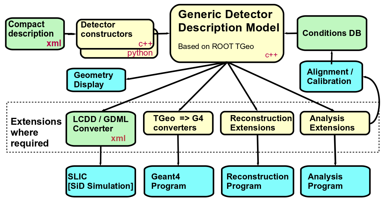
Figure 1.1 shows the architecture of the main components of the toolkit and their interfaces to the end-user applications, namely the simulation, reconstruction, alignment and visualization. The central element of the toolkit is the so-called generic detector description model. This is an in-memory model, i.e., a set of C++ objects holding the data describing the geometry and other information of the detector. The rest of the toolkit consists of tools and interfaces to input or output information from this generic detector model. The model and its components will be described in subsequence sections.
1.2.1 The Compact Detector Description
Inspired from the work of the linear collider detector simulation [9], the compact detector description is used to define an ideal detector as typically used during the conceptual design phase of an experiment. The compact description in its minimalistic form is probably not going to be adequate later in the detector life cycle and is likely to be replaced or refined when a more realistic detector with deviations from the ideal would be needed by the experiment.
In the compact description the detector is parametrized in minimalistic terms with user provided parameters in XML. XML is an open format, the DD4hep parsers do not validate against a fix schema and hence allow to easily introduce new elements and attributes to describe detectors. This feature minimizes the burden on the end-user while still supporting flexibility.
Such a compact detector descriptions cannot be interpreted in a general manner, therefore so called Detector Constructors are needed.
1.2.2 Detector Constructors
Detector Constructors are relatively small code fragments that get as input an XML element from the compact description that represents a single detector instance. The code interprets the data and expands its geometry model in memory using the elements from the generic detector description model described in section 1.3. The toolkit invokes these code fragments in a data driven way using naming conventions during the initialization phase of the application. Users focus on one single detector type at the time, but the toolkit supports them to still construct complex and large detector setups. Two implementations are currently supported: One is based on C++, which performs better and is able to detect errors at compiler time, but the code is slightly more technical. The other is based on Python fragments, the code is more readable and compact but errors are only detected at execution time.
The compact description together with the detector constructors are sufficient to build the detector model and to visualize it. If during the lifetime of the experiment the detector model changes, the corresponding constructors will need to be adapted accordingly. DD4hep provides already a palette of basic pre-implemented geometrical detector concepts to design experiments. In view of usage of DD4hep as a detector description toolkit, this library may in the future also adopt generic designs of detector components created by end users e.g. during the design phase of future experiments.
1.3 Generic Detector Description Model
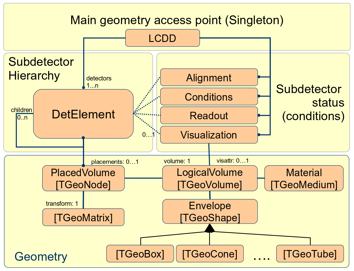
This is the heart of the DD4hep detector description toolkit. Its purpose is to build in memory a model of the detector including its geometrical aspects as well as structural and functional aspects. The design reuses the elements from the ROOT geometry package and extends them in case required functionality is not available. Figure 1.2 illustrates the main players and their relationships. Any detector is modeled as a tree of Detector Elements, the entity central to this design, which is represented in the implementation by the DetElement class [2]. It offers all applications a natural entry point to any detector part of the experiment and represents a complete sub-detector (e.g. TPC), a part of a sub-detector (e.g. TPC-Endcap), a detector module or any other convenient detector device. The main purpose is to give access to the data associated to the detector device. For example, if the user writes some TPC reconstruction code, accessing the TPC detector element from this code will provide access the all TPC geometrical dimensions, the alignment and calibration constants and other slow varying conditions such as the gas pressure, end-plate temperatures etc. The Detector Element acts as a data concentrator. Applications may access the full experiment geometry and all connected data through a singleton object called Detector, which provides management, bookkeeping and ownership to the model instances.
The geometry is implemented using the ROOT geometry classes, which are used directly without unnecessary interfaces to isolate the end-user from the actual ROOT based implementation. There is one exception: The constructors are wrapped to facilitate a very compact and readable notation to end-users building custom Detector Constructors.
1.3.1 Detector Element Tree versus the Geometry Hierarchy
The geometry part of the detector description is delegated to the ROOT classes. Logical Volumes are the basic objects used in building the geometrical hierarchy. A Logical Volume is a shape with its dimensions and consist of a given material. They represent unpositioned objects which store all information about the placement of possibly embedded volumes. The same volume can be replicated several times in the geometry. The Logical Volume also represents a system of reference with respect to its containing volumes. The reuse of instances of Logical Volumes for different placements optimizes the memory consumption and detailed geometries for complex setups consisting of millions of volumes may be realized with reasonable amount of memory. The difficulty is to identify a given positioned volume in space and e.g. applying misalignment to one of these volumes. The relationship between the Detector Element and the placements is not defined by a single reference to the placement, but the full path from the top of the detector geometry model to resolve existing ambiguities due to the reuse of Logical Volumes. Hence, individual volumes must be identified by their full path from mother to daughter starting from the top-level volume.
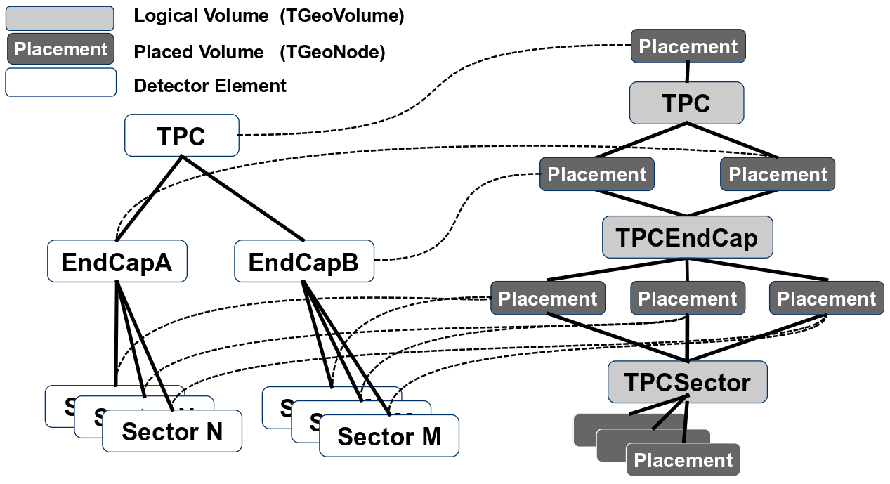
The tree structure of Detector Elements is a parallel structure to the geometrical hierarchy. This structure will probably not be as deep as the geometrical one since there would not need to associate detector information at very fine-grain level - it is unlikely that every little metallic screw needs associated detector information such as alignment, conditions, etc. Though this screw and many other replicas must be described in the geometry description since it may be important e.g. for its material contribution in the simulation application. Thus, the tree of Detector Elements is fully degenerate and each detector element object will be placed only once in the detector element tree as illustrated for a hypothetical TPC detector in Figure 1.3.
1.3.2 Extensions and Views
As depicted in Figure 1.1 the reconstruction application will require special functionality extending the basics offered by the common detector element. This functionality may be implemented by a set of specialized classes that will extend the detector element. These extensions will be in charge of providing specific answers to the questions formulated by the reconstruction algorithms such as pattern recognition, tracking, vertexing, particle identification, etc. One example could be to transform a calorimeter cell identifier into a 3D space position in the global coordinate system. A generic detector description toolkit would be unable to answer this concrete question, however it provides a convenient environment for the developer to slot-in code fragments, which implement the additional functionality using parameters stored in the XML compact description.
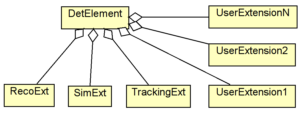
Depending on the functionality these specialized component must be able to either store additional data, expose additional behavior or both. Additional behavior may easily be added overloading the DetElement class using its internal data. The internal data is public and addressed by reference, hence any number of views extending the DetElement behavior may be constructed with very small overhead. Additional data may be added by any user at any time to any instance of the DetElement class using a simple aggregation mechanism shown in Figure 1.4. Data extensions must differ by their type. The freedom to attach virtually any data item allows for optimized attachments depending on the application type, such as special attachments for reconstruction, simulation, tracking, etc.
This design allows to build views addressing the following use-cases:
- Convenience Views
-
provide higher level abstractions and internally group complex calculations. Such views simplify the life of the end-users.
- Optimization Views
-
allows end-users extend the data of the common detector detector element and store precomputed results, which would be expensive to obtain repeatedly.
- Compatibility Views
-
help to ensure smooth periods of software redesign. During the life-time of the experiment often various software constructs are for functional reasons re-designed and re-engineered. Compatibility Views either adapt new data designs to existing application code or expose new behavior based on existing data.
1.4 Simulation Support
Detector-simulation depends strongly on the use of an underlying simulation toolkit, the most prominent candidate nowadays being Geant4 [8]. DD4hep supports simulation activities with Geant4 providing an automatic translation mechanism between geometry representations. The simulation response in the active elements of the detector is not implemented by the toolkit, since it is strongly influenced by the technical choices and precise simulations depends on the very specific detection techniques. In Geant4 this response is computed in software constructs called Sensitive Detectors.
Ideally DD4hep aims to provide a generic simulation application. Similar to the palette of pre-implemented geometrical detector concepts to design experiments, it provides a palette of Sensitive Detectors to simulate the detector response in form of a component library. Detector designers may base the simulation of a planned experiment on these predefined components for initial design and optimization studies. In a similar way easy access and configuration of other user actions of Geant4 is provided.
1.5 Detector Alignment Support
The support for alignment operations is crucial to the usefulness of the toolkit. In the linear collider community this support is basically missing in all the currently used geometry description systems. The possibility to apply into the detector description alignment deltas (differences with respect the ideal or measured position) and read them from an external source is mandatory to exploit the toolkit. A typical alignment application would consist of calculating a new set of deltas from a given starting point, which could then be loaded and applied again in order to validate the alignment by recalculating some alignment residuals. The ROOT geometry package supports to apply an [mis]-alignment to touchable objects in the geometry. Touchable objects are identified by the path of positioned volumes starting with the top node (e.g. path=). Contrary to ordinary multiple placements of Logical Volumes, touchable objects are degenerate and only valid for one single volume [6]. To simplify the usage for the end user, the identification of a positioned volume will be connected to the Detector Element, where only the relative path with respect to the Detector Element will have to be specified rather the full path from the top volume. The delta-values will have to be read from various data sources. The initial implementation will be based on simple XML files, later a connection to other sources such as the detector conditions database is envisaged.