2 Surfaces
2.2 Surface implementation
2.3 Using surfaces in geometry constructors
2.4 Using surfaces in reconstruction code
2.5 Visualizing detector surfaces
For fitting the trajectories of charged particle tracks one generally needs to know the measurement surfaces on which the hits where deposited. Additionally the material properties along the trajectory need to be known in order to correct for effects from multiple scattering and energy loss. DDRec provides an abstract interface for surfaces and materials in the namespace DDSurfaces and a concrete implementation, described below, in the namespace DDRec. This is done in order to separate interface and implementation and allow other software tools, e.g. tracking packages to just use the interface.
2.1 namespace DDSurfaces
The basic concept of surfaces in DDRec is expressed with the two main interfaces ISurface and IMaterial. They are shown together with helper classes in the DDSurfaces in figure:1 and are briefly described in the following.
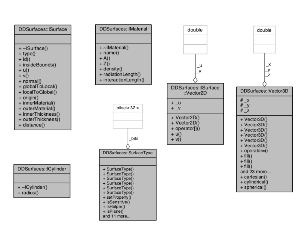
ISurface: Defines the surface by means of an origin, a normal vector n and two, typically orthogonal, direction vectors u and v, where all of the vectors n,u,v might depend on the actual position on (or close to) the surface. In order to describe material properties two thicknesses are assigned to the surface - one in direction of the normal vector (outerThickness) and one in the opposite direction (innerThickness). There are two materials assigned to these thicknesses, where these materials could be averaged along the normal and thickness. The method isInsideBounds allows in principle to implement arbitrary bounds for the surface. Two methods allow the conversion between global 3d coordinates (on the surface) and local 2d coordinates in the coordinate system of the surface.
IMaterial: Interface to describe the relevant material properties: atomic number and weight, density and radiation- and interaction lengths. These can be real materials or averaged materials along a given direction and length (thickness assigned to the surface).
ICylinder: Simple interface for cylindrical surfaces adding the cylinder radius to a surface through multiple inheritance.
ISurface::Vector2D Helper struct inside ISurface for 2d vectors with coordinates u and v.
Vector3D: Generic 3d vector class with cartesian coordinates x,y,z that allows initialization from other 3d vector implementations or using cylindrical or spherical coordinates. Provides access to quantities often needed, such as magnitude, transversal component, representation in non-cartesian coordinates.
SurfaceType: Helper class using an std::bitfield¡32¿ to encode the following properties of the surface: isCylinder, isPlane, isSensitive, isHelper (dead material), isParallelToZ, isOrthogonalToZ, isInvisible, isMeasurement1D.
2.2 Surface implementation
DDRec provides classes that implement the interface defined in DDSurfaces. The main classes for implementing ISurface are shown in figure 2.
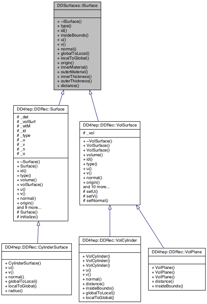
The implementation of the surfaces in DDRec is done in two parallel hierarchies of implementation classes. The first hierarchy is based on the VolSurface class which connects a surface with its surrounding volume. This volume then provide the boundaries of the surface and gives access to the local to global coordinate transformations inside the coordinate system of the volume. There are currently two concrete implementations: VolCylinder and VolPlane that can be used in the detector construction code as described in2.3. The second hierarchy is the actual implementation of the surface concept in DDRec to be used by reconstruction code as described in 2.4. It uses the extension and views concept described in the main manual[2]. The Surface class has a VolSurface object and a DetElement and uses these to establish the local to global coordinate transforms, the surface boundaries and the material properties. The materials on both sides of the surface are the averaged materials along the direction of the normal with the given thicknesses. It is thus possible to also take material effects into account for materials that lay outside of the actual volume the surface is attached to. This is in particular useful for compound materials that consist of a larger number of thin slices.
2.3 Using surfaces in geometry constructors
The surfaces that should be available in the reconstruction code, have to be assigned to their corresponding volume and detector element by the user in the detector geometry construction code. This is done by specifying the coordinate system and orientation of the surface inside the volume with vectors o,n,u and v and then instantiating one of the two types VolCylinder or VolPlane for a given volume. After the placement of the corresponding DetElement, the surface is added to the list of surfaces for this DetElement.
This is demonstrated in the following example code:
#include "DDRec/Surface.h" //... // base vectors for surfaces: DDSurfaces::Vector3D o(0,0,0) ; DDSurfaces::Vector3D u(1,0,0) ; DDSurfaces::Vector3D v(0,1,0) ; DDSurfaces::Vector3D n(0,0,1) ; // --- loop over layers ---- // ... DD4hep::Geometry::Box box( dimX/2, dimY/2, dimZ/2 ) ; DD4hep::Geometry::Volume vol( volumeName, lcdd.material( x_layer.materialStr() )) ; DD4hep::Geometry::DetElement layerDetElement( parentDetElement , "layer"+_toString(i,"_%02d") , det_id ) ; // add a measurement surface to the layer for every sensitive slice: DD4hep::DDRec::VolPlane surf( vol , DDSurfaces::SurfaceType(DDSurfaces::SurfaceType::Sensitive), dimZ, dimZ, u, v, n , o ) ; // place the layer DD4hep::Geometry::PlacedVolume pv = parentVol.placeVolume( vol, layerPlacement ); layerDetElement.setPlacement( pv ) ; DD4hep::DDRec::volSurfaceList( layerDetElement )->push_back( surf ) ; // --- end loop over layers ----
In this example a planar (VolPlane) measurement (SurfaceType(Sensitive)) surface is attached to the box volume of a detector layer. The thickness of the surface corresponds to that of the box and is given by its half length in z ( Vector3D n(0,0,1) runs along z). Thus the surface is completely contained in the box and no averaging of materials will be done, unless additional volumes are placed inside the box at a later stage. The origin of the coordinate system of the surface coincides with that of the box (Vector3D o(0,0,0); ) and the two measurement directions u,v run along the x and y axis of the box respectively.
The following code snipped shows the creation of a cylindrical surface attached to a tube volume for the inner field cage of a tpc. The radius of the cylindrical surface is given by the transversal component of the origin vector ocyl. The volume innerWallVol is filled with air and will be later populated with slices of a compound material, thus the material properties will be averaged along the thickness of the tube.
//... DD4hep::Geometry::Tube innerWallSolid(rInner ,rInner + dr_InnerWall ,dz_Wall / 2.0 ) ; DD4hep::Geometry::Volume innerWallVol( "TPCInnerWallVol", innerWallSolid, materialAir ) ; pv = tpc_motherLog.placeVolume( innerWallVol ) ; DDSurfaces::Vector3D ocyl( rInner + 0.5*dr_InnerWall , 0. , 0. ) ; DD4hep::DDRec::VolCylinder surfI( innerWallVol , SurfaceType( SurfaceType::Helper ) , 0.5*dr_InnerWall, 0.5*dr_InnerWall, ocyl ) ; volSurfaceList( tpc )->push_back( surfI ) ; //...
2.4 Using surfaces in reconstruction code
Accessing and using the surfaces in reconstruction code is very easy. There are two possibilities to access the surfaces:
-
use the DetectorSurfaces view class to get a list of all surfaces that have been assigned to a particular DetElement object.
-
or use the SurfaceManager class to get a list of all surfaces of a given DetElement and all its daughters.
The following code snippet uses the SurfaceManager, initialized with the world DetElement, to get a list of all surfaces defined for a given detector model. The surfaces are then printed to std::cout and filled into a map, using the surfaces ID as a key. For sensitive surfaces, attached to sensitive volumes, the ID will be that of the sensitive volume and thus such a map provides a very easy lookup from the hitID to its corresponding measurement surface.
// ... DD4hep::Geometry::LCDD& lcdd = DD4hep::Geometry::LCDD::getInstance(); lcdd.fromCompact( inFile ); DD4hep::Geometry::DetElement world = lcdd.world() ; // create a list of all surfaces in the detector: DD4hep::DDRec::SurfaceManager surfMan( world ) ; const DD4hep::DDRec::SurfaceList& sL = surfMan.surfaceList() ; // map of surfaces std::map< long64, DD4hep::DDRec::Surface* > surfMap ; for( DD4hep::DDRec::SurfaceList::const_iterator it = sL.begin() ; it != sL.end() ; ++it ){ DD4hep::DDRec::Surface* surf = *it ; std::cout << " ------------------------- " << " surface: " << *surf << std::endl << " ------------------------- " << std::endl ; surfMap[ surf->id() ] = surf ; }
And similarly this code uses the DetectorSurfaces class to just access the surfaces for a particular detector element:
// ... DD4hep::Geometry::DetElement ladderDE = lcdd.detector("VXD_layer02_ladder42") ; // create surfaces DD4hep::DDRec::DetectorSurfaces ds( ladderDE ) ; const DD4hep::DDRec::SurfaceList& detSL = ds.surfaceList() ; for( DD4hep::DDRec::SurfaceList::const_iterator it = detSL.begin() ; it != detSL.end() ; ++it ){ DD4hep::DDRec::Surface* surf = *it ; std::cout << " ------------------------- " << " surface: " << *surf << std::endl << " ------------------------- " << std::endl ; }
2.5 Visualizing detector surfaces
The detector surfaces and the vectors defining their coordinate system can be visualized with the program teveDisplay that is part of . In a future version of this visualization might be included in . Currently a full 3d view of the detector surfaces as well as a -view and a -z view are available. See figure 3.
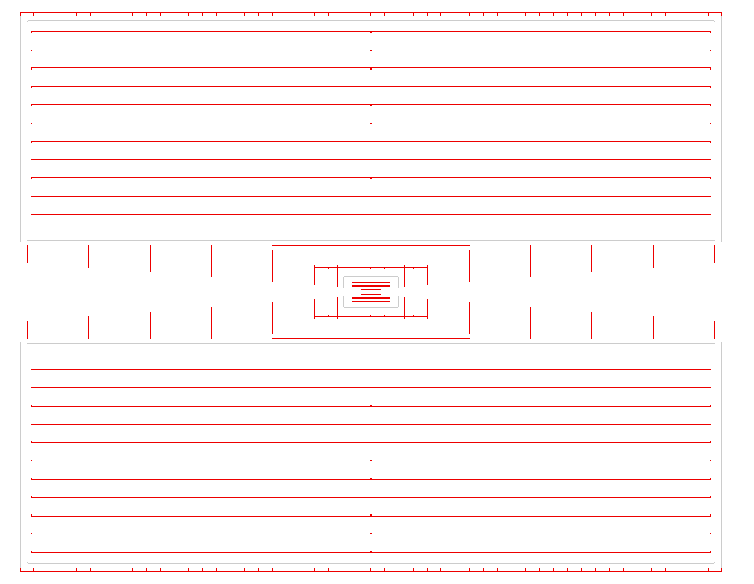
![]()